METER / GAUGE / DISPLAY METER / GAUGE SYSTEM(for TFT Meter Type) Speed Signal Circuit
DESCRIPTION
FOR HV MODEL
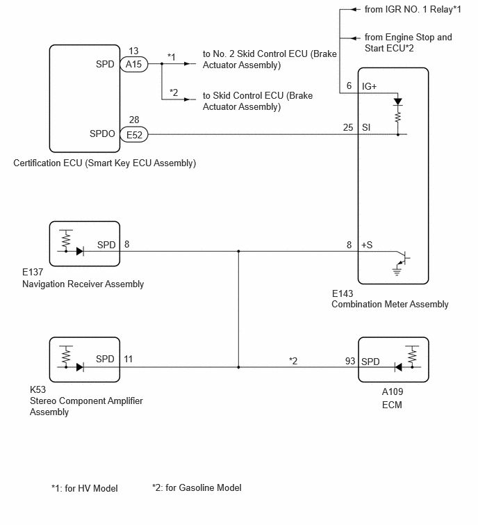
The combination meter assembly receives the vehicle speed signal from this circuit. The wheel speed sensors produce an output that varies according to the vehicle speed. The wheel speed sensor output is received by the No. 2 skid control ECU (brake actuator assembly) which uses this information to create the vehicle speed signal. The vehicle speed signal consists of pulses sent to the combination meter assembly from the No. 2 skid control ECU (brake actuator assembly). To create this signal, 12 V is output from the combination meter assembly. This voltage is sent to the No. 2 skid control ECU (brake actuator assembly). The pulse signal is created by switching the transistor in the No. 2 skid control ECU (brake actuator assembly) on and off, making the voltage on the wire drop to 0 V. A similar system is used for the output of this signal from the combination meter assembly via terminal +S. A voltage of 12 V is applied to terminal +S from each ECU or relay that is connected to this terminal. The transistor in the combination meter assembly is controlled by the signal from the No. 2 skid control ECU (brake actuator assembly). When this transistor is turned on, this transistor makes the voltage supplied by the various ECUs (via their respective internal resistors) drop to 0 V. Each ECU connected to terminal +S of the combination meter assembly controls its respective system based on this pulse signal.
FOR GASOLINE MODEL
The combination meter assembly receives the vehicle speed signal from this circuit. The wheel speed sensors produce an output that varies according to the vehicle speed. The wheel speed sensor output is received by the skid control ECU (brake actuator assembly) which uses this information to create the vehicle speed signal. The vehicle speed signal consists of pulses sent to the combination meter assembly from the skid control ECU (brake actuator assembly). To create this signal, 12 V is output from the combination meter assembly. This voltage is sent to the skid control ECU (brake actuator assembly). The pulse signal is created by switching the transistor in the skid control ECU (brake actuator assembly) on and off, making the voltage on the wire drop to 0 V. A similar system is used for the output of this signal from the combination meter assembly via terminal +S. A voltage of 12 V is applied to terminal +S from each ECU or relay that is connected to this terminal. The transistor in the combination meter assembly is controlled by the signal from the skid control ECU (brake actuator assembly). When this transistor is turned on, this transistor makes the voltage supplied by the various ECUs (via their respective internal resistors) drop to 0 V. Each ECU connected to terminal +S of the combination meter assembly controls its respective system based on this pulse signal.
WIRING DIAGRAM
CAUTION / NOTICE / HINT
- NOTICE:
- ·
When replacing the combination meter assembly, always replace it with a new one. If a combination meter assembly which was installed to another vehicle is used, the information stored in it will not match the information from the vehicle and a DTC may be stored.
·When replacing any of the following ECUs, update the ECU security key.
-Combination meter assembly
-Certification ECU (smart key ECU assembly)
·Before replacing the certification ECU (smart key ECU assembly), refer to Service Bulletin.
·When the electronically controlled brake system is malfunctioning, a correct vehicle speed signal may not be received. Before preforming this procedure, confirm that the electronically controlled brake system is not malfunctioning.
for HV Model: Click hereBrake>BRAKE CONTROL / DYNAMIC CONTROL SYSTEMS>ELECTRONICALLY CONTROLLED BRAKE SYSTEM (for HV Model)>HOW TO PROCEED WITH TROUBLESHOOTING202111,999999,_54,_111814,_0500671,RM100000001Z2YP,
for Gasoline Model: Click hereBrake>BRAKE CONTROL / DYNAMIC CONTROL SYSTEMS>ELECTRONICALLY CONTROLLED BRAKE SYSTEM (for Gasoline Model)>HOW TO PROCEED WITH TROUBLESHOOTING202111,999999,_54,_111814,_0503031,RM100000001ZCXQ,
PROCEDURE
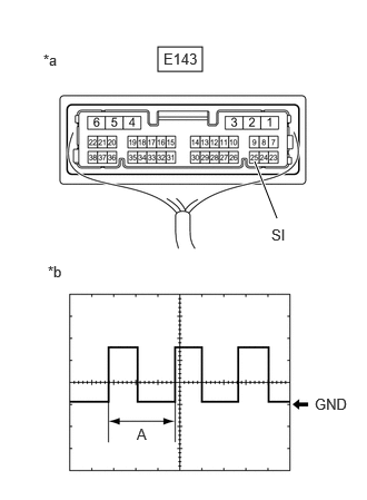
| *a | Component with harness connected
(Combination Meter Assembly) |
| *b | Waveform |
Check the signal waveform according to the condition(s) in the table below.
| Item | Condition |
|---|---|
| Tester connection | E143-25 (SI) - Body ground |
| Tool setting | 5 V/DIV., 20 ms./DIV. |
| Condition | Ignition switch ON, wheel being rotated |
- HINT:
-
When the system is functioning normally, one wheel revolution generates 4 pulses. As the vehicle speed increases, the width indicated by (A) in the illustration narrows.
- Result:
Result Proceed to The measured waveform is similar to that in the illustration A The measured waveform is not similar to that in the illustration
(Stuck low)B The measured waveform is not similar to that in the illustration
(Stuck high)C
A
B
C
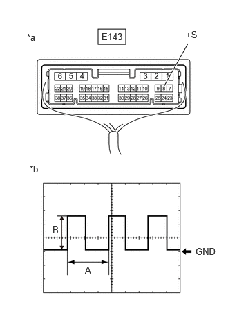
| *a | Component with harness connected
(Combination Meter Assembly) |
| *b | Waveform |
Check the signal waveform according to the condition(s) in the table below.
| Item | Condition |
|---|---|
| Tester connection | E143-8 (+S) - Body ground |
| Tool setting | 5 V/DIV., 20 ms./DIV. |
| Condition | Ignition switch ON, wheel being rotated |
- HINT:
- ·
When the system is functioning normally, one wheel revolution generates 4 pulses. As the vehicle speed increases, the width indicated by (A) in the illustration narrows.
·The waveform (B) changes depending on the connected ECUs.
- Result:
Result Proceed to The measured waveform is similar to that in the illustration A The measured waveform is not similar to that in the illustration
(Stuck low)B The measured waveform is not similar to that in the illustration
(Stuck high)C
A
B
C
Disconnect the A109 ECM connector.*
Disconnect the E137 navigation receiver assembly connector.
Disconnect the K53 stereo component amplifier assembly connector.
Disconnect the E143 combination meter assembly connector.
Measure the resistance according to the value(s) in the table below.
- Standard Resistance:
Tester Connection Condition Specified Condition Click Location & Routing(A109,E143,E137,K53)Location & Routingewd_type=routing;type=c,c,c,c;code=A109,E143,E137,K53
Click Connector(A109)Engine Compartment>Engine Room Main Wire / Transmission Wire>ECMewd_type=component;type=c;code=A109;pinno=93
Click Connector(E143)Instrument Panel>Instrument Panel Wire / Telephone Computer Wire>Combination Meter Assemblyewd_type=component;type=c;code=E143;pinno=8
Click Connector(E137)Instrument Panel>Instrument Panel Wire / Telephone Computer Wire>Navigation Receiver Assemblyewd_type=component;type=c;code=E137;pinno=8
Click Connector(K53)Body>Floor Wire>Stereo Component Amplifier Assemblyewd_type=component;type=c;code=K53;pinno=11
A109-93 (SPD) - E143-8 (+S)* Always Below 1 Ω E137-8 (SPD) - E143-8 (+S) Always Below 1 Ω K53-11 (SPD) - E143-8 (+S) Always Below 1 Ω
*: for Gasoline Model
- Result:
Proceed to OK NG
OK
NG
Disconnect one of the connectors below.
- NOTICE:
-
After disconnecting a connector, perform all steps with all other ECUs connected.
| Connector | ECU |
|---|---|
| A109* | ECM |
| E137 | Navigation receiver assembly |
| K53 | Stereo component amplifier assembly |
*: for Gasoline Model
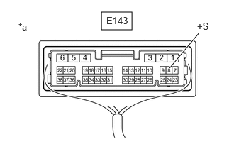
| *a | Component with harness connected
(Combination Meter Assembly) |
Measure the voltage according to the value(s) in the table below.
- NOTICE:
-
Make sure to perform this inspection with the wheels stopped.
- Standard Voltage:
Tester Connection Condition Specified Condition Click Location & Routing(E143)Location & Routingewd_type=routing;type=c;code=E143
Click Connector(E143)Instrument Panel>Instrument Panel Wire / Telephone Computer Wire>Combination Meter Assemblyewd_type=component;type=c;code=E143;pinno=8
E143-8 (+S) - Body ground Ignition switch ON 4.5 to 14 V
Repeat steps (a) and (b) for each connected ECU.
- HINT:
-
If the voltage changed to the specified voltage after disconnecting a connector, an internal short in the disconnected ECU is suspected.
- Result:
Result Proceed to After performing the inspection procedure for all connectors, the voltage did not change to the specified voltage A When disconnecting the connector of the ECM, the voltage changed to the specified voltage
(for Gasoline Model)B When disconnecting the connector of the navigation receiver assembly, the voltage changed to the specified voltage C When disconnecting the connector of the stereo component amplifier assembly, the voltage changed to the specified voltage D
A
B
C
D
Disconnect the A109 ECM connector.*
Disconnect the E137 navigation receiver assembly connector.
Disconnect the K53 stereo component amplifier assembly connector.
Disconnect the E143 combination meter assembly connector.
Measure the resistance according to the value(s) in the table below.
- Standard Resistance:
Tester Connection Condition Specified Condition Click Location & Routing(A109,E137,K53,E143)Location & Routingewd_type=routing;type=c,c,c,c;code=A109,E137,K53,E143
Click Connector(A109)Engine Compartment>Engine Room Main Wire / Transmission Wire>ECMewd_type=component;type=c;code=A109;pinno=93
Click Connector(E137)Instrument Panel>Instrument Panel Wire / Telephone Computer Wire>Navigation Receiver Assemblyewd_type=component;type=c;code=E137;pinno=8
Click Connector(K53)Body>Floor Wire>Stereo Component Amplifier Assemblyewd_type=component;type=c;code=K53;pinno=11
Click Connector(E143)Instrument Panel>Instrument Panel Wire / Telephone Computer Wire>Combination Meter Assemblyewd_type=component;type=c;code=E143;pinno=8
A109-93 (SPD)*, E137-8 (SPD) or K53-11 (SPD) - E143-8 (+S) Always Below 1 Ω A109-93 (SPD)*, E137-8 (SPD), K53-11 (SPD) or E143-8 (+S) - Body ground Always 10 kΩ or higher
*: for Gasoline Model
- Result:
Proceed to OK NG
OK
NG
Check if smart entry and start system (for start function) DTCs are output.
- Body Electrical > Power Source Control > Trouble Codes
- 50001 454
- Result:
Result Proceed to DTCs are not output A DTCs are output B
A
B
for HV Model: Click hereVehicle Interior>THEFT DETERRENT / KEYLESS ENTRY>SMART ENTRY AND START SYSTEM (for Start Function, HV Model)>DIAGNOSTIC TROUBLE CODE CHART202111,999999,_58,_111832,_0509384,RM10000000204YB,
for Gasoline Model: Click hereVehicle Interior>THEFT DETERRENT / KEYLESS ENTRY>SMART ENTRY AND START SYSTEM (for Start Function, Gasoline Model)>DIAGNOSTIC TROUBLE CODE CHART202303,999999,_58,_111832,_0509385,RM100000002BLPK,
- HINT:
-
This procedure is performed to check the diode inside the combination meter assembly.
Remove the combination meter assembly.
Measure the internal resistance of the combination meter assembly.
- Standard Resistance:
Tester Connection Tester Connection Condition Measured Value Click Location & Routing(E143)Location & Routingewd_type=routing;type=c;code=E143
Click Connector(E143)Instrument Panel>Instrument Panel Wire / Telephone Computer Wire>Combination Meter Assemblyewd_type=component;type=c;code=E143;pinno=6,25
E143-6 (IG+) - E143-25 (SI) ·Positive (+) tester probe → E143-6 (IG+)
·Negative (-) tester probe → E143-25 (SI)
Always A E143-6 (IG+) - E143-25 (SI) ·Positive (+) tester probe → E143-25 (SI)
·Negative (-) tester probe → E143-6 (IG+)
Always B
- OK:
There is a large difference between the measured value (A) and the measured value (B).
- Result:
Proceed to OK NG
OK
NG
Disconnect the E52 certification ECU (smart key ECU assembly) connector.
Disconnect the E143 combination meter assembly connector.
Measure the resistance according to the value(s) in the table below.
- Standard Resistance:
Tester Connection Condition Specified Condition Click Location & Routing(E52,E143)Location & Routingewd_type=routing;type=c,c;code=E52,E143
Click Connector(E52)Instrument Panel>Instrument Panel Wire / Telephone Computer Wire>Smart Key ECU Assemblyewd_type=component;type=c;code=E52;pinno=28
Click Connector(E143)Instrument Panel>Instrument Panel Wire / Telephone Computer Wire>Combination Meter Assemblyewd_type=component;type=c;code=E143;pinno=25
E52-28 (SPDO) or E143-25 (SI) - Body ground Always 10 kΩ or higher
- Result:
Proceed to OK NG
OK
NG
Check if smart entry and start system (for start function) DTCs are output.
- Body Electrical > Power Source Control > Trouble Codes
- 50001 454
- Result:
Result Proceed to DTCs are not output A DTCs are output B
A
B
for HV Model: Click hereVehicle Interior>THEFT DETERRENT / KEYLESS ENTRY>SMART ENTRY AND START SYSTEM (for Start Function, HV Model)>DIAGNOSTIC TROUBLE CODE CHART202111,999999,_58,_111832,_0509384,RM10000000204YB,
for Gasoline Model: Click hereVehicle Interior>THEFT DETERRENT / KEYLESS ENTRY>SMART ENTRY AND START SYSTEM (for Start Function, Gasoline Model)>DIAGNOSTIC TROUBLE CODE CHART202303,999999,_58,_111832,_0509385,RM100000002BLPK,
Disconnect the E52 certification ECU (smart key ECU assembly) connector.
Disconnect the E143 combination meter assembly connector.
Measure the resistance according to the value(s) in the table below.
- Standard Resistance:
Tester Connection Condition Specified Condition Click Location & Routing(E52,E143)Location & Routingewd_type=routing;type=c,c;code=E52,E143
Click Connector(E52)Instrument Panel>Instrument Panel Wire / Telephone Computer Wire>Smart Key ECU Assemblyewd_type=component;type=c;code=E52;pinno=28
Click Connector(E143)Instrument Panel>Instrument Panel Wire / Telephone Computer Wire>Combination Meter Assemblyewd_type=component;type=c;code=E143;pinno=25
E52-28 (SPDO) - E143-25 (SI) Always Below 1 Ω
- Result:
Proceed to OK NG
OK
NG