SUPPLEMENTAL RESTRAINT SYSTEMS AIRBAG SYSTEM B009787 Right Side Restraints Sensor 2 Missing Message
DESCRIPTION
| DTC No. | Detection Item | DTC Detection Condition | Trouble Area | Warning Indicate | DTC Output from | Priority | Test Mode / Check Mode |
|---|---|---|---|---|---|---|---|
| B009787 | Right Side Restraints Sensor 2 Missing Message | ·
The airbag sensor assembly detects a line short circuit signal, open circuit signal, short circuit to ground signal or short circuit to +B signal in the side collision sensor RH circuit (bus 2) for 2 seconds. ·
Floor side airbag sensor RH malfunction ·
Airbag sensor assembly malfunction |
·
Harness or connector ·
Floor side airbag sensor RH ·
Airbag sensor assembly |
Comes on | SRS Airbag | A | Does not apply to test/check mode |
WIRING DIAGRAM
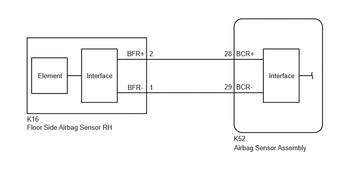
CAUTION / NOTICE / HINT
- NOTICE:
- ·
After the ignition switch is turned off, there may be a waiting time before disconnecting the negative (-) auxiliary battery terminal.
·When disconnecting and reconnecting the auxiliary battery.
- HINT:
-
When disconnecting and reconnecting the auxiliary battery, there is an automatic learning function that completes learning when the respective system is used.
·After replacing the airbag sensor assembly, refer to work procedure.
PROCEDURE
Pre-procedure1
Turn the ignition switch off.
Disconnect the cable from the negative (-) auxiliary battery terminal, and wait for at least 60 seconds.
Procedure1
Check that the connectors are properly connected to the airbag sensor assembly and floor side airbag sensor RH.
- OK:
The connectors are properly connected.
- Result:
Proceed to OK NG
Post-procedure1
None
OK
NG
Pre-procedure1
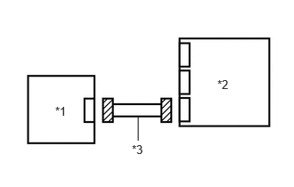
| *1 | Floor Side Airbag Sensor RH |
| *2 | Airbag Sensor Assembly |
| *3 | Wire Harness |
Disconnect the airbag sensor assembly connector.
Disconnect the floor side airbag sensor RH connector.
Procedure1
Check that the terminals of the connectors are not deformed or damaged.
- OK:
The terminals are not deformed or damaged.
- Result:
Proceed to OK NG
Post-procedure1
None
OK
NG
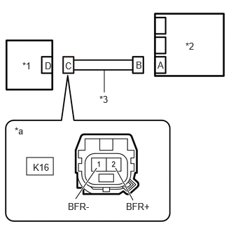
| *1 | Floor Side Airbag Sensor RH |
| *2 | Airbag Sensor Assembly |
| *3 | Wire Harness |
| *a | Front view of wire harness connector
(to Floor Side Airbag Sensor RH) |
Measure the resistance according to the value(s) in the table below.
- Standard Resistance:
Tester Connection Condition Specified Condition Click Location & Routing(K16)Location & Routingewd_type=routing;type=c;code=K16
Click Connector(K16)Body>Floor Wire>Floor Side Airbag Sensor RHewd_type=component;type=c;code=K16;pinno=2,1
K16-2 (BFR+) - K16-1 (BFR-) Always 1 MΩ or higher
- Result:
Proceed to OK NG
OK
NG
Pre-procedure1
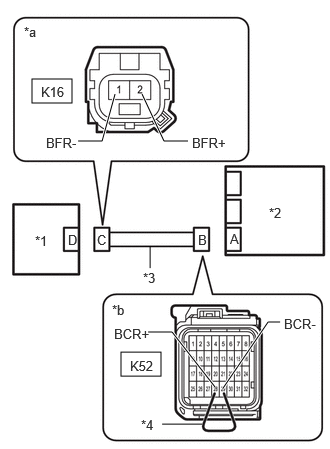
| *1 | Floor Side Airbag Sensor RH |
| *2 | Airbag Sensor Assembly |
| *3 | Wire Harness |
| *4 | Service Wire |
| *a | Front view of wire harness connector
(to Floor Side Airbag Sensor RH) |
| *b | Front view of wire harness connector
(to Airbag Sensor Assembly) |
Using a service wire, connect terminals 28 (BCR+) and 29 (BCR-) of connector B.
- NOTICE:
-
Do not forcibly insert the service wire into the terminals of the connector when connecting a service wire.
Procedure1
Measure the resistance according to the value(s) in the table below.
- Standard Resistance:
Tester Connection Condition Specified Condition Click Location & Routing(K16)Location & Routingewd_type=routing;type=c;code=K16
Click Connector(K16)Body>Floor Wire>Floor Side Airbag Sensor RHewd_type=component;type=c;code=K16;pinno=2,1
K16-2 (BFR+) - K16-1 (BFR-) Always Below 1 Ω
- Result:
Proceed to OK NG
Post-procedure1
Disconnect the service wire from connector B.
OK
NG
| *1 | Floor Side Airbag Sensor RH |
| *2 | Airbag Sensor Assembly |
| *3 | Wire Harness |
| *a | Front view of wire harness connector
(to Floor Side Airbag Sensor RH) |
Measure the resistance according to the value(s) in the table below.
- Standard Resistance:
Tester Connection Condition Specified Condition Click Location & Routing(K16)Location & Routingewd_type=routing;type=c;code=K16
Click Connector(K16)Body>Floor Wire>Floor Side Airbag Sensor RHewd_type=component;type=c;code=K16;pinno=2,1
K16-2 (BFR+) - Body ground Always 1 MΩ or higher K16-1 (BFR-) - Body ground Always 1 MΩ or higher
- Result:
Proceed to OK NG
OK
NG
Pre-procedure1
Connect the cable to the negative (-) auxiliary battery terminal, and wait for at least 2 seconds.
Turn the ignition switch to ON.
Procedure1
| *1 | Floor Side Airbag Sensor RH |
| *2 | Airbag Sensor Assembly |
| *3 | Wire Harness |
| *a | Front view of wire harness connector
(to Floor Side Airbag Sensor RH) |
Measure the voltage according to the value(s) in the table below.
- Standard Voltage:
Tester Connection Condition Specified Condition Click Location & Routing(K16)Location & Routingewd_type=routing;type=c;code=K16
Click Connector(K16)Body>Floor Wire>Floor Side Airbag Sensor RHewd_type=component;type=c;code=K16;pinno=2,1
K16-2 (BFR+) - Body ground Ignition switch ON Below 1 V K16-1 (BFR-) - Body ground Ignition switch ON Below 1 V
- Result:
Proceed to OK NG
Post-procedure1
Turn the ignition switch off.
Disconnect the cable from the negative (-) auxiliary battery terminal, and wait for at least 60 seconds.
OK
NG
Pre-procedure1
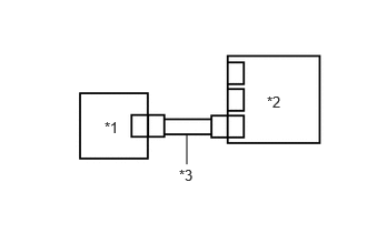
| *1 | Floor Side Airbag Sensor LH |
| *2 | Airbag Sensor Assembly |
| *3 | Wire Harness |
Connect the airbag sensor assembly connector.
Interchange the floor side airbag sensor RH with LH and connect the connectors to them.
Connect the cable to the negative (-) auxiliary battery terminal, and wait for at least 2 seconds.
Turn the ignition switch to ON, and wait for at least 60 seconds.
Procedure1
Clear the DTCs stored in memory.
- Body Electrical > SRS Airbag > Clear DTCs
- 50002 444
- Result:
Proceed to NEXT
Post-procedure1
Turn the ignition switch off.
NEXT
Pre-procedure1
Turn the ignition switch to ON, and wait for at least 60 seconds.
Procedure1
Check for DTCs.
- Body Electrical > SRS Airbag > Trouble Codes
- 50001 444
- Result:
Result Proceed to B009787 is output A B009287 is output B B009287 and B009787 are not output C
- HINT:
-
Codes other than DTCs B009287 and B009787 may be output at this time, but they are not related to this check.
Post-procedure1
Turn the ignition switch off.
Disconnect the cable from the negative (-) auxiliary battery terminal, and wait for at least 60 seconds.
Return the floor side airbag sensor LH and RH to their original positions and connect the connectors to them.
A
B
C