ADVANCED DRIVER ASSISTANCE SYSTEM PRE-COLLISION SYSTEM U023587 Lost Communication with Cruise Control Front Distance Range Sensor Missing Message
DESCRIPTION
The forward recognition camera communicates with the millimeter wave radar sensor assembly via CAN communication. If a communication malfunction between the forward recognition camera and millimeter wave radar sensor assembly is detected, DTC U023587 is stored.
| DTC No. | Detection Item | DTC Detection Condition | Trouble Area | DTC Output from | Priority |
|---|---|---|---|---|---|
| U023587 | Lost Communication with Cruise Control Front Distance Range Sensor Missing Message | Once 3 seconds elapse after turning the ignition switch to ON, a communication malfunction between the millimeter wave radar sensor assembly continues for approximately 2 seconds or more. | ·
Harness or connector ·
Forward recognition camera ·
Millimeter wave radar sensor assembly |
Pre-Collision System | A |
| Pattern | DTC output part name
(Display on GTS) |
Suspected Area (Malfunction Status) | ||||
|---|---|---|---|---|---|---|
| Forward Recognition Camera | Millimeter Wave Radar Sensor Assembly | |||||
| Pre-Collision System | Lane Control | Forward Recognition Camera (Front Lighting Control) | Radar Cruise2 | Front Radar Sensor | ||
| U023587 | U023587 | U023587 | U023587 | U010487 | ||
|
○: DTC is output -: DTC is not output |
||||||
| Pattern 1 | ○ | ○ | ○ | ○ | ○ | Harness or connector (Open or short) |
| Millimeter wave radar sensor assembly (Internal malfunction) | ||||||
| Forward recognition camera (Internal malfunction) | ||||||
| Pattern 2 | ○ | ○ | ○ | ○ | - | Forward recognition camera (Internal malfunction) |
| Millimeter wave radar sensor assembly (Internal malfunction) | ||||||
- HINT:
-
If the DTCs are output simultaneously, the inspection area can be narrowed down.
WIRING DIAGRAM
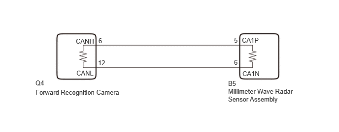
CAUTION / NOTICE / HINT
- NOTICE:
- ·
When replacing the millimeter wave radar sensor assembly, always replace it with a new one. If a millimeter wave radar sensor assembly which was installed to another vehicle is used, the information stored in the millimeter wave radar sensor assembly will not match the information from the vehicle and a DTC may be stored.
·When the millimeter wave radar sensor assembly has been replaced with a new one, it is necessary to perform millimeter wave radar sensor assembly beam axis alignment and to clear the vehicle control history. Before performing the Driving Adjustment, make sure to read Before Starting Driving Adjustment.
- HINT:
-
Beam axis alignment of the millimeter wave radar sensor assembly can be performed using either Triangle Target, Flat Surface Target or Driving Adjustment.
-
Triangle Target: Click hereADAS / AD>ADVANCED DRIVER ASSISTANCE SYSTEM>MILLIMETER WAVE RADAR SENSOR>TARGET ADJUSTMENT(TRIANGLE TARGET)202303,999999,_95,_111850,_0502179,RM10000000292SE,
-
Flat Surface Target: Click hereADAS / AD>ADVANCED DRIVER ASSISTANCE SYSTEM>MILLIMETER WAVE RADAR SENSOR>TARGET ADJUSTMENT(FLAT SURFACE TARGET)202303,999999,_95,_111850,_0502179,RM10000000292SF,
-
Driving Adjustment: Click hereADAS / AD>ADVANCED DRIVER ASSISTANCE SYSTEM>MILLIMETER WAVE RADAR SENSOR>DRIVING ADJUSTMENT202303,999999,_95,_111850,_0502179,RM10000000292SD,
·When replacing the forward recognition camera, always replace it with a new one. If a forward recognition camera which was installed to another vehicle is used, the information stored in the forward recognition camera will not match the information from the vehicle. As a result, a DTC may be stored.
·When the forward recognition camera is replaced with a new one or the windshield glass is replaced or removed/installed, make sure to read Before Starting Adjustment, then perform optical axis alignment for the forward recognition camera and clear the vehicle control history for each system.
- HINT:
-
Forward recognition camera axis alignment can be performed by using either One Time Recognition, Sequential Recognition or Driving Adjustment.
-
One Time Recognition: Click hereADAS / AD>ADVANCED DRIVER ASSISTANCE SYSTEM>FRONT CAMERA>TARGET ADJUSTMENT(ONE TIME RECOGNITION)202303,999999,_95,_111850,_0502177,RM10000000292S8,
-
Sequential Recognition: Click hereADAS / AD>ADVANCED DRIVER ASSISTANCE SYSTEM>FRONT CAMERA>TARGET ADJUSTMENT(SEQUENTIAL RECOGNITION)202303,999999,_95,_111850,_0502177,RM10000000292S9,
-
Driving Adjustment: Click hereADAS / AD>ADVANCED DRIVER ASSISTANCE SYSTEM>FRONT CAMERA>DRIVING ADJUSTMENT202303,999999,_95,_111850,_0502177,RM10000000292SB,
·When the forward recognition camera is replaced, update the ECU security key.
·After the ignition switch is turned off, there may be a waiting time before disconnecting the negative (-) auxiliary battery terminal.
·When disconnecting and reconnecting the auxiliary battery
- HINT:
-
When disconnecting and reconnecting the auxiliary battery, there is an automatic learning function that completes learning when the respective system is used.
PROCEDURE
Read each DTC and check the diagnosis pattern using the table below.
- Body Electrical > Pre-Collision System > Trouble Codes
- 50001 432
- Chassis > Lane Control > Trouble Codes
- 50001 418
- Body Electrical > Front Recognition Camera (Front Lighting Control) > Trouble Codes
- 50001 433
- Powertrain > Radar Cruise2 > Trouble Codes
- 50001 426
- Body Electrical > Front Radar Sensor > Trouble Codes
- 50001 429
| Pattern | DTC output part name
(Display on GTS) |
||||
|---|---|---|---|---|---|
| Pre-Collision System | Lane Control | Forward Recognition Camera (Front Lighting Control) | Radar Cruise2 | Front Radar Sensor | |
| Pattern 1 | U023587 | U023587 | U023587 | U023587 | U010487 |
| Pattern 2 | U023587 | U023587 | U023587 | U023587 | - |
- Result:
Result Proceed to Pattern 1 A Pattern 2 B
A
B
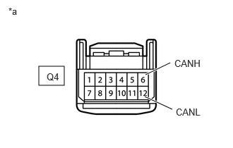
| *a | Front view of wire harness connector
(to Forward Recognition Camera) |
Disconnect the cable from the negative (-) auxiliary battery terminal.
Disconnect the forward recognition camera connector.
Measure the resistance according to the value(s) in the table below.
- Standard Resistance:
Tester Connection Condition Specified Condition Click Location & Routing(Q4)Location & Routingewd_type=routing;type=c;code=Q4
Click Connector(Q4)Body>Roof Wire>Forward Recognition Cameraewd_type=component;type=c;code=Q4;pinno=6,12
Q4-6 (CANH) - Q4-12 (CANL) Cable disconnected from negative (-) auxiliary battery terminal 108 to 132 Ω Q4-6 (CANH) - Body ground Cable disconnected from negative (-) auxiliary battery terminal 200 Ω or higher Q4-12 (CANL) - Body ground Q4-6 (CANH) - +B Cable disconnected from negative (-) auxiliary battery terminal 6 kΩ or higher Q4-12 (CANL) - +B
- Result:
Proceed to OK NG
OK
NG

| *a | Front view of wire harness connector
(to Millimeter Wave Radar Sensor Assembly) |
Disconnect the cable from the negative (-) auxiliary battery terminal.
Connect the forward recognition camera connector.
Disconnect the millimeter wave radar sensor assembly connector.
Measure the resistance according to the value(s) in the table below.
- Standard Resistance:
Tester Connection Condition Specified Condition Click Location & Routing(B5)Location & Routingewd_type=routing;type=c;code=B5
B5-5 (CA1P) - B5-6 (CA1N) Cable disconnected from negative (-) auxiliary battery terminal 108 to 132 Ω B5-5 (CA1P) - Body ground Cable disconnected from negative (-) auxiliary battery terminal 200 Ω or higher B5-6 (CA1N) - Body ground B5-5 (CA1P) - +B Cable disconnected from negative (-) auxiliary battery terminal 6 kΩ or higher B5-6 (CA1N) - +B
- Result:
Proceed to OK NG
OK
NG
| *a | Front view of wire harness connector
(to Forward Recognition Camera) |
Disconnect the forward recognition camera connector.
Using an oscilloscope, check the waveform.
- OK:
Tester Connection Condition Tool Setting Specified Condition Click Location & Routing(Q4)Location & Routingewd_type=routing;type=c;code=Q4
Click Connector(Q4)Body>Roof Wire>Forward Recognition Cameraewd_type=component;type=c;code=Q4;pinno=6,12
Q4-6 (CANH) - Q4-12 (CANL) Ignition switch ON 1 V/DIV., 100 μs./DIV. Pulse generation
- Result:
Proceed to OK NG
OK
NG