INTERIOR PANELS / TRIM ROOF HEADLINING INSTALLATION
PROCEDURE

 66425B
1.INSTALL REAR NO. 2 SIDE RAIL SPACER LH
66425B
1.INSTALL REAR NO. 2 SIDE RAIL SPACER LH
- HINT:
-
Perform this procedure only when replacement of the rear No. 2 side rail spacer LH is necessary.
Engage the guide and 2 claws to install the rear No. 2 side rail spacer LH.
66415B
2.INSTALL REAR NO. 2 SIDE RAIL SPACER RH
- HINT:
-
Use the same procedure as for the LH side.
3.INSTALL ROOF HEADLINING ASSEMBLY
for Short Type Panoramic Fixed Moon Roof:
Put the roof headlining assembly into the vehicle through the front passenger door as shown in the illustration.
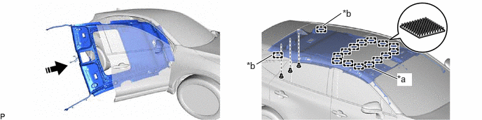
| *a | Fastener | *b | Guide |

|
Install in this Direction | - | - |
- NOTICE:
-
Do not damage the roof headlining assembly or vehicle interior.
Engage the 2 guides and 14 fasteners.
Install the roof headlining assembly with the 3 clips.
for Long Type Panoramic Fixed Moon Roof:
Put the roof headlining assembly into the vehicle through the front passenger door as shown in the illustration.
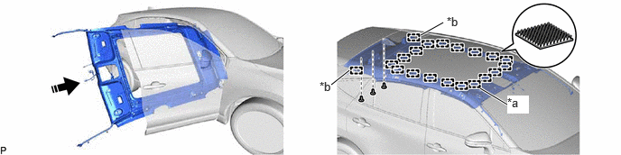
| *a | Fastener | *b | Guide |
|
|
Install in this Direction | - | - |
- NOTICE:
-
Do not damage the roof headlining assembly or vehicle interior.
Engage the 2 guides and 18 fasteners.
Install the roof headlining assembly with the 3 clips.
for Front Pillar LH Side:
Remove the protective cover.
Engage the 2 clamps.
Connect each connector.
Install the protective cover.
for Front Pillar RH Side:
Remove the protective cover.
Engage the 2 clamps.
Connect the connector.
Install the protective cover.
for Windshield Glass Side:
Connect each connector.
for Map Light Side with Long Type Panoramic Fixed Moon Roof:
Connect the connector.
for Rear Pillar LH Side with Digital Inner Mirror:
Connect the connector.
for Rear Pillar RH Side:
Connect the connector.
4.INSTALL COVER (w/ ETC)
Engage the 4 claws to install the cover.
89943
5.INSTALL RAIN SENSOR COVER (w/ Rain Sensor)
86466D
6.INSTALL NO. 1 FORWARD RECOGNITION COVER
86466E
7.INSTALL NO. 2 FORWARD RECOGNITION COVER
81340
8.INSTALL VANITY LIGHT ASSEMBLY
81240
9.INSTALL NO. 1 ROOM LIGHT ASSEMBLY
10.INSTALL MAP LIGHT ASSEMBLY
74610A
11.INSTALL ASSIST GRIP SUB-ASSEMBLY
- HINT:
-
Use the same procedure for all assist grip sub-assemblies.
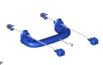
| *a | Assist Grip |
Install the 2 clips to the assist grip.
Temporarily install the assist grip cover LH and assist grip cover RH to the assist grip as shown in the illustration.
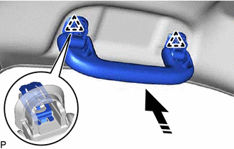
|
|
Install in this Direction |
Engage the 2 clips to install the assist grip sub-assembly as shown in the illustration.

Engage the 4 claws to install the assist grip cover LH and assist grip cover RH.
- NOTICE:
-
Make sure that the clips are engaged securely.
74630E
12.INSTALL REAR ASSIST GRIP ASSEMBLY LH
- HINT:
-
Use the same procedure as for the assist grip sub-assembly.
74620C
13.INSTALL REAR ASSIST GRIP ASSEMBLY RH
- HINT:
-
Use the same procedure as for the assist grip sub-assembly.
14.INSTALL VISOR HOLDER
- HINT:
-
Use the same procedure for the LH side and RH side.
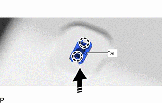
| *a | Base of Visor Holder |
|
|
Install in this Direction |
Engage the 2 claws to install the base of visor holder as shown in the illustration.
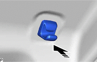
|
|
Install in this Direction |
Install the visor holder as shown in the illustration.
74320
15.INSTALL VISOR ASSEMBLY LH
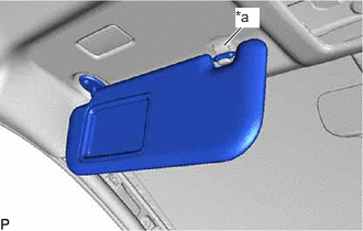
| *a | Visor Holder |
Connect the visor assembly LH to the visor holder.
Install the visor assembly LH with the 2 screws.
74325
16.INSTALL VISOR BRACKET COVER LH
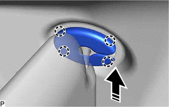
|
|
Install in this Direction |
Engage the 4 claws to install the visor bracket cover LH.
74310
17.INSTALL VISOR ASSEMBLY RH
- HINT:
-
Use the same procedure as for the LH side.
74325
18.INSTALL VISOR BRACKET COVER RH
- HINT:
-
Use the same procedure as for the LH side.
58996A
19.INSTALL NO. 2 CONSOLE BOX MOUNTING BRACKET
Install the No. 2 console box mounting bracket with the 4 bolts.
- Torque:
- 15 N*m (153 kgf*cm, 11 ft.*lbf)
Engage the 2 clamps.
Connect the connector.
20.INSTALL TRANSMISSION FLOOR SHIFT ASSEMBLY
for P710:Click hereDrivetrain>P710 (HYBRID TRANSMISSION / TRANSAXLE)>SHIFT LEVER>INSTALLATION202203,999999,_52,_111805,_0503481,RM1000000021ZNL,
for K120:Click hereDrivetrain>K120 / K120F / K121 / K121F (CVT)>SHIFT LEVER>INSTALLATION202203,202303,_52,_111806,_0499742,RM1000000022726,202303,999999,_52,_111806,_0499742,RM100000002B6JT,
62480A
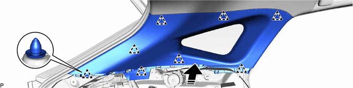
21.INSTALL ROOF SIDE INNER GARNISH ASSEMBLY LH
Install 8 new clips to the roof side inner garnish assembly LH.
- HINT:
-
Make sure that the clip is engaged correctly.
Engage the 8 clips to install the roof side inner garnish assembly LH as shown in the illustration.
|
|
Install in this Direction | - | - |
62470A
22.INSTALL ROOF SIDE INNER GARNISH ASSEMBLY RH
- HINT:
-
Use the same procedure as for the LH side.
64740C
23.INSTALL DECK TRIM SIDE PANEL ASSEMBLY LH
Engage the 5 guides, 2 clips and 5 claws.
Install the deck trim side panel assembly LH with the clip and screw.
64730B
24.INSTALL DECK TRIM SIDE PANEL ASSEMBLY RH
Engage the 5 guides, 2 clips and 5 claws.
Install the deck trim side panel assembly RH with the clip and screw.
81330
25.INSTALL NO. 1 LUGGAGE COMPARTMENT LIGHT ASSEMBLY
62552F
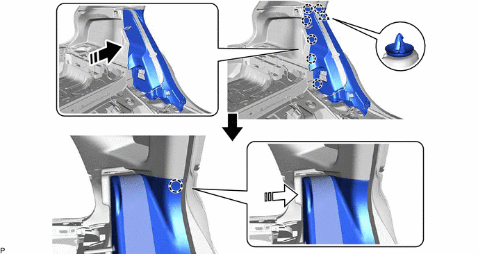
26.INSTALL REAR SEAT SIDE GARNISH LH
Engage the clip and 6 claws as shown in the illustration.
|
|
Install in this Direction (1) | 
|
Install in this Direction (2) |
Engage the claw to install the rear seat side garnish LH as shown in the illustration.
62551F
27.INSTALL REAR SEAT SIDE GARNISH RH
- HINT:
-
Use the same procedure as for the LH side.
71304C
28.INSTALL REAR SEATBACK HINGE SUB-ASSEMBLY LH
Install the rear seatback hinge sub-assembly LH with the 2 bolts.
- Torque:
- 36.8 N*m (375 kgf*cm, 27 ft.*lbf)
71303C
29.INSTALL REAR SEATBACK HINGE SUB-ASSEMBLY RH
- HINT:
-
Use the same procedure as for the LH side.
73706
30.INSTALL CHILD RESTRAINT SEAT ANCHOR BRACKET SUB-ASSEMBLY LH
73705
31.INSTALL CHILD RESTRAINT SEAT ANCHOR BRACKET SUB-ASSEMBLY RH
- HINT:
-
Use the same procedure as for the LH side.
58577E
32.INSTALL REAR NO. 1 FLOOR MAT SUPPORT SIDE PLATE
Engage the 2 claws and 4 clips.
Install the rear No. 1 floor mat support side plate with the 2 screws.
58387B
33.INSTALL REAR FLOOR FINISH PLATE
Engage the 2 guides, 2 claws and 4 clips to install the rear floor finish plate.
62420A
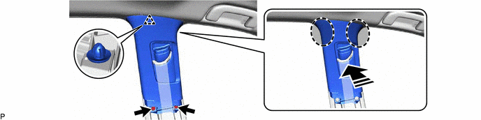
34.INSTALL CENTER PILLAR GARNISH ASSEMBLY LH
Install a new clip to the center pillar garnish assembly LH.
Pass the anchor of the front seat outer belt assembly LH through the center pillar garnish assembly LH.
Engage the clip as shown in the illustration.
Install the center pillar garnish assembly LH with the 2 clips.
|
|
Install in this Direction | - | - |
62410A
35.INSTALL CENTER PILLAR GARNISH ASSEMBLY RH
- HINT:
-
Use the same procedure as for the LH side.
62414A
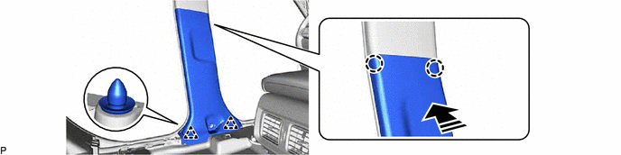
36.INSTALL CENTER PILLAR LOWER GARNISH LH
Engage the 2 clips and 2 claws to install the center pillar lower garnish LH as shown in the illustration.
|
|
Install in this Direction | - | - |
62413A
37.INSTALL CENTER PILLAR LOWER GARNISH RH
- HINT:
-
Use the same procedure as for the LH side.
73220
38.CONNECT FRONT SEAT OUTER BELT ASSEMBLY LH
73233
39.INSTALL LAP BELT OUTER ANCHOR COVER (for LH Side)
73210
40.CONNECT FRONT SEAT OUTER BELT ASSEMBLY RH
- HINT:
-
Use the same procedure as for the LH side.
73233
41.INSTALL LAP BELT OUTER ANCHOR COVER (for RH Side)
- HINT:
-
Use the same procedure as for the LH side.
62332C
42.INSTALL REAR DOOR OPENING TRIM WEATHERSTRIP LH
62331C
43.INSTALL REAR DOOR OPENING TRIM WEATHERSTRIP RH
- HINT:
-
Use the same procedure as for the LH side.
58466J
44.INSTALL NO. 2 BATTERY SERVICE COVER BOARD (for HV Model)
Engage the 2 guides and 5 clips as shown in the illustration.

|
|
Install in this Direction | - | - |
Install the No. 2 battery service cover board with the 2 clips.
58467H
45.INSTALL NO. 3 BATTERY SERVICE COVER BOARD (for HV Model)
Engage the 2 guides and 5 clips as shown in the illustration.

|
|
Install in this Direction | - | - |
Install the No. 3 battery service cover board with the 2 clips.
67918A
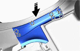
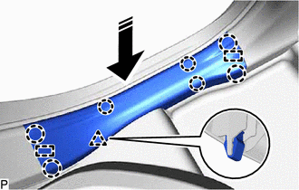
46.INSTALL REAR DOOR SCUFF PLATE LH
for Gasoline Model:
|
|
Install in this Direction |
Engage the 2 guides and 6 claws as shown in the illustration to install the rear door scuff plate LH.
for HV Model:
|
|
Install in this Direction |
Engage the 2 guides, clip and 7 claws as shown in the illustration to install the rear door scuff plate LH.
67917A
47.INSTALL REAR DOOR SCUFF PLATE RH
- HINT:
-
Use the same procedure as for the LH side.
62212
48.INSTALL FRONT PILLAR GARNISH LH
Remove the protective cover.
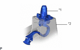
| *1 | Front Pillar Garnish Clip |
| *2 | Front Pillar Garnish LH |
Install 2 new front pillar garnish clips to the front pillar garnish LH.
- HINT:
-
Make sure that the front pillar garnish clip is engaged correctly.
w/ Front No. 2 Speaker:
Connect the connector.
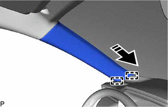
|
|
Install in this Direction |
Push the front pillar garnish LH as shown in the illustration to engage the 2 guides.
|
|
Install in this Direction |
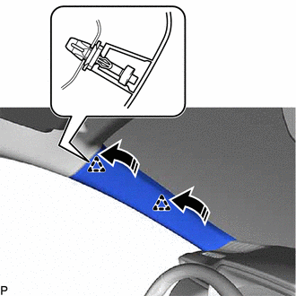
Engage the 2 front pillar garnish clips to install the front pillar garnish LH as shown in the illustration.
- HINT:
-
Make sure that the curtain shield airbag assembly LH is not pinched.
62211
49.INSTALL FRONT PILLAR GARNISH RH
- HINT:
-
Use the same procedure as for the LH side.
62312B
50.INSTALL FRONT DOOR OPENING TRIM WEATHERSTRIP LH
62311B
51.INSTALL FRONT DOOR OPENING TRIM WEATHERSTRIP RH
- HINT:
-
Use the same procedure as for the LH side.
62112A
52.INSTALL COWL SIDE TRIM SUB-ASSEMBLY LH
|
|
Install in this Direction |
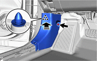
Engage the clip as shown in the illustration.
Install the cowl side trim sub-assembly LH with the clip.
62111C
53.INSTALL COWL SIDE TRIM BOARD RH
- HINT:
-
Use the same procedure as for the LH side.
67914B
54.INSTALL FRONT DOOR SCUFF PLATE LH
w/ Illumination:
Connect the connector.
|
|
Install in this Direction |
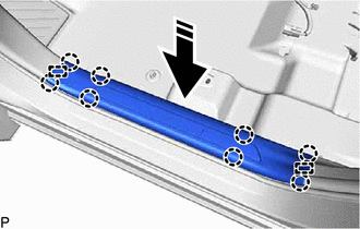
Engage the 2 guides and 8 claws to install the front door scuff plate LH.
67913B
55.INSTALL FRONT DOOR SCUFF PLATE RH
- HINT:
-
Use the same procedure as for the LH side.
56.INSTALL REAR SEAT ASSEMBLY
64779
57.INSTALL SPARE WHEEL COVER TRAY
Install the spare wheel cover tray.
65351A
58.INSTALL BATTERY HOLE COVER
Engage the 8 claws to install the battery hole cover.
58417
59.INSTALL REAR NO. 3 FLOOR BOARD
Engage the 3 clips to install the rear No. 3 floor board.
58416K
60.INSTALL REAR NO. 2 FLOOR BOARD
Engage the 3 clips to install the rear No. 2 floor board.
58410B
61.INSTALL DECK BOARD ASSEMBLY
Install the deck board assembly.
62.INSTALL FRONT SEAT ASSEMBLY
for Manual Seat:
for Power Seat: