SEAT CLIMATE CONTROL SEAT SYSTEM Climate Control Seat System does not Operate
DESCRIPTION
When the ignition switch is on and the climate control switch is operated, the air conditioning amplifier assembly receives climate control switch position signals and then sends airflow amount signals to each seat climate control blower.
WIRING DIAGRAM
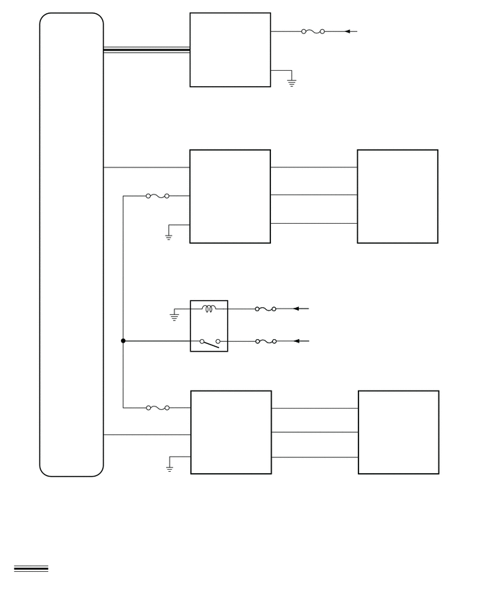
CAUTION / NOTICE / HINT
- NOTICE:
- ·
Inspect the fuses for circuits related to this system before performing the following procedure.
·If the auxiliary battery voltage becomes low, auxiliary battery load control will operate in order to ensure sufficient power is supplied to the power steering system. In this case, the climate control seat system may not operate.
·The climate control seat system uses the LIN communication system. Inspect the communication function by following How to Proceed with Troubleshooting. Troubleshoot the climate control seat system after confirming that the communication system is functioning properly.
PROCEDURE
Clear DTCs.
- Body Electrical > Air Conditioner > Clear DTCs
- 50002 450
Check for DTCs.
- Body Electrical > Air Conditioner > Trouble Codes
- 50001 450
- Result:
Result Proceed to DTC B14B587 is not output A DTC B14B587 output B
A
B
Check the climate control seat operation.
- Result:
Result Proceed to Climate control seat does not operate (for LH) A Climate control seat does not operate (for RH) B Both climate control seats do not operate C
A
B
C
Perform the Active Test according to the display on the GTS.
- Body Electrical > Air Conditioner > Active Test
-
Tester Display Measurement Item Control Range Diagnostic Note Front Left Seat Blower Front LH seat blower operation OFF or ON -
- Body Electrical > Air Conditioner > Active Test
-
Tester Display Front Left Seat Blower - 50004 450 22
- OK:
The seat blower operates normally.
- Result:
Result Proceed to Only seatback climate control blower LH A Only seat cushion climate control blower LH does not operate B Both seat blowers do not operate C
A
B
for SFTM Made: Click hereVehicle Interior>SEAT>FRONT SEAT ASSEMBLY (for SFTM Made Power Seat)>DISASSEMBLY202111,999999,_58,_111839,_0500775,RM100000001Z3EH,
for GTMC Made: Click hereVehicle Interior>SEAT>FRONT SEAT ASSEMBLY (for GTMC Made Power Seat)>DISASSEMBLY202203,999999,_58,_111839,_0525811,RM10000000229GJ,
C
Disconnect the V11 seatback climate control blower LH connector.
Disconnect the U39 seat cushion climate control blower LH connector.
Measure the resistance according to the value(s) in the table below.
- Standard Resistance:
Tester Connection Condition Specified Condition Click Location & Routing(V11,U39)Location & Routingewd_type=routing;type=c,c;code=V11,U39
Click Connector(V11)Seat>No. 2 Front Seat Wire RH / No. 2 Front Seat Wire LH>Seatback Climate Control Blower LHewd_type=component;type=c;code=V11;pinno=1,3,4
Click Connector(U39)Seat>Front Seat Wire RH / Front Seat Wire LH>Seat Cushion Climate Control Blower Assembly LHewd_type=component;type=c;code=U39;pinno=5,6,4
V11-1 (CTB) - U39-5 (CTB) Always Below 1 Ω V11-1 (CTB) or U39-5 (CTB) - Body ground Always 10 kΩ or higher V11-3 (BFB+) - U39-6 (BFB+) Always Below 1 Ω V11-3 (BFB+) or U39-6 (BFB+) - Body ground Always 10 kΩ or higher V11-4 (BFB-) - U39-4 (BFB-) Always Below 1 Ω V11-4 (BFB-) or U39-4 (BFB-) - Body ground Always 10 kΩ or higher
- Result:
Proceed to OK NG
OK
NG
Temporarily replace the seatback climate control blower LH with a new or known good one.
for SFTM Made: Click hereVehicle Interior>SEAT>FRONT SEAT ASSEMBLY (for SFTM Made Power Seat)>DISASSEMBLY202111,999999,_58,_111839,_0500775,RM100000001Z3EH,
for GTMC Made: Click hereVehicle Interior>SEAT>FRONT SEAT ASSEMBLY (for GTMC Made Power Seat)>DISASSEMBLY202203,999999,_58,_111839,_0525811,RM10000000229GJ,
- Result:
Proceed to NEXT
NEXT
Check the climate control seat operation.
- OK:
The climate control seat operates normally.
- Result:
Proceed to OK NG
OK
NG
for SFTM Made: Click hereVehicle Interior>SEAT>FRONT SEAT ASSEMBLY (for SFTM Made Power Seat)>DISASSEMBLY202111,999999,_58,_111839,_0500775,RM100000001Z3EH,
for GTMC Made: Click hereVehicle Interior>SEAT>FRONT SEAT ASSEMBLY (for GTMC Made Power Seat)>DISASSEMBLY202203,999999,_58,_111839,_0525811,RM10000000229GJ,
Disconnect the U39 seat cushion climate control blower LH connector.
Measure the voltage and resistance according to the value(s) in the table below.
- Standard Voltage:
Tester Connection Condition Specified Condition Click Location & Routing(U39)Location & Routingewd_type=routing;type=c;code=U39
Click Connector(U39)Seat>Front Seat Wire RH / Front Seat Wire LH>Seat Cushion Climate Control Blower Assembly LHewd_type=component;type=c;code=U39;pinno=1
U39-1 (IG) - Body ground Ignition switch ON 11 to 14 V U39-1 (IG) - Body ground Ignition switch off Below 1 V
- Standard Resistance:
Tester Connection Condition Specified Condition Click Location & Routing(U39)Location & Routingewd_type=routing;type=c;code=U39
Click Connector(U39)Seat>Front Seat Wire RH / Front Seat Wire LH>Seat Cushion Climate Control Blower Assembly LHewd_type=component;type=c;code=U39;pinno=8
U39-8 (GND) - Body ground Always Below 1 Ω
- Result:
Proceed to OK NG
OK
NG
Disconnect the E44 air conditioning amplifier assembly connector.
Measure the resistance according to the value(s) in the table below.
- Standard Resistance:
Tester Connection Condition Specified Condition Click Location & Routing(U39,E44)Location & Routingewd_type=routing;type=c,c;code=U39,E44
Click Connector(U39)Seat>Front Seat Wire RH / Front Seat Wire LH>Seat Cushion Climate Control Blower Assembly LHewd_type=component;type=c;code=U39;pinno=7
Click Connector(E44)Instrument Panel>Instrument Panel Wire / Radio Wiring Sub-Assy / Telephone Computer Wire>Air Conditioning Amplifier Assemblyewd_type=component;type=c;code=E44;pinno=14
U39-7 (SIGN) - E44-14 (LOUT) Always Below 1 Ω U39-7 (SIGN) or E44-14 (LOUT) - Body ground Always 10 kΩ or higher
- Result:
Proceed to OK NG
OK
NG
Reconnect the E44 air conditioning amplifier assembly connector.
| *a | Component with harness connected
(Air Conditioning Amplifier Assembly) |
Reconnect the U39 seat cushion climate control blower LH connector.
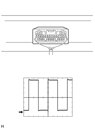
Using an oscilloscope, check the input signal waveform.
| Item | Content |
|---|---|
| Tester Connection | E44-14 (LOUT) - Body ground |
| Tool Setting | 1 V/DIV., 0.5 ms/DIV. |
| Vehicle Condition | ·
Ignition switch ON ·
Climate control switch (for LH) on (blower position) |
- OK:
Waveform is similar to that shown in the illustration.
- Result:
Proceed to OK NG
OK
for SFTM Made: Click hereVehicle Interior>SEAT>FRONT SEAT ASSEMBLY (for SFTM Made Power Seat)>DISASSEMBLY202111,999999,_58,_111839,_0500775,RM100000001Z3EH,
for GTMC Made: Click hereVehicle Interior>SEAT>FRONT SEAT ASSEMBLY (for GTMC Made Power Seat)>DISASSEMBLY202203,999999,_58,_111839,_0525811,RM10000000229GJ,
NG
Perform the Active Test according to the display on the GTS.
- Body Electrical > Air Conditioner > Active Test
-
Tester Display Measurement Item Control Range Diagnostic Note Front Right Seat Blower Front RH seat blower operation OFF or ON -
- Body Electrical > Air Conditioner > Active Test
-
Tester Display Front Right Seat Blower - 50004 450 21
- OK:
The seat blower operates normally.
- Result:
Result Proceed to Only seatback climate control blower RH does not operate A Only seat cushion climate control blower RH does not operate B Both seat blowers do not operate C
A
B
for SFTM Made: Click hereVehicle Interior>SEAT>FRONT SEAT ASSEMBLY (for SFTM Made Power Seat)>DISASSEMBLY202111,999999,_58,_111839,_0500775,RM100000001Z3EH,
for GTMC Made: Click hereVehicle Interior>SEAT>FRONT SEAT ASSEMBLY (for GTMC Made Power Seat)>DISASSEMBLY202203,999999,_58,_111839,_0525811,RM10000000229GJ,
C
Disconnect the V1 seatback climate control blower RH connector.
Disconnect the U7 seat cushion climate control blower RH connector.
Measure the resistance according to the value(s) in the table below.
- Standard Resistance:
Tester Connection Condition Specified Condition Click Location & Routing(V1,U7)Location & Routingewd_type=routing;type=c,c;code=V1,U7
Click Connector(V1)Seat>No. 2 Front Seat Wire RH / No. 2 Front Seat Wire LH>Seatback Climate Control Blower RHewd_type=component;type=c;code=V1;pinno=1,3,4
Click Connector(U7)Seat>Front Seat Wire RH / Front Seat Wire LH>Seat Cushion Climate Control Blower Assembly RHewd_type=component;type=c;code=U7;pinno=5,6,4
V1-1 (CTB) - U7-5 (CTB) Always Below 1 Ω V1-1 (CTB) or U7-5 (CTB) - Body ground Always 10 kΩ or higher V1-3 (BFB+) - U7-6 (BFB+) Always Below 1 Ω V1-3 (BFB+) or U7-6 (BFB+) - Body ground Always 10 kΩ or higher V1-4 (BFB-) - U7-4 (BFB) Always Below 1 Ω V1-4 (BFB-) or U7-4 (BFB) - Body ground Always 10 kΩ or higher
- Result:
Proceed to OK NG
OK
NG
Temporarily replace the seatback climate control blower RH with a new or known good one.
for SFTM Made: Click hereVehicle Interior>SEAT>FRONT SEAT ASSEMBLY (for SFTM Made Power Seat)>DISASSEMBLY202111,999999,_58,_111839,_0500775,RM100000001Z3EH,
for GTMC Made: Click hereVehicle Interior>SEAT>FRONT SEAT ASSEMBLY (for GTMC Made Power Seat)>DISASSEMBLY202203,999999,_58,_111839,_0525811,RM10000000229GJ,
- Result:
Proceed to NEXT
NEXT
Check the climate control seat operation.
- OK:
The climate control seat operates normally.
- Result:
Proceed to OK NG
OK
NG
for SFTM Made: Click hereVehicle Interior>SEAT>FRONT SEAT ASSEMBLY (for SFTM Made Power Seat)>DISASSEMBLY202111,999999,_58,_111839,_0500775,RM100000001Z3EH,
for GTMC Made: Click hereVehicle Interior>SEAT>FRONT SEAT ASSEMBLY (for GTMC Made Power Seat)>DISASSEMBLY202203,999999,_58,_111839,_0525811,RM10000000229GJ,
Disconnect the U7 seat cushion climate control blower RH connector.
Measure the voltage and resistance according to the value(s) in the table below.
- Standard Voltage:
Tester Connection Condition Specified Condition Click Location & Routing(U7)Location & Routingewd_type=routing;type=c;code=U7
Click Connector(U7)Seat>Front Seat Wire RH / Front Seat Wire LH>Seat Cushion Climate Control Blower Assembly RHewd_type=component;type=c;code=U7;pinno=1
U7-1 (+BAT) - Body ground Ignition switch ON 11 to 14 V U7-1 (+BAT) - Body ground Ignition switch off Below 1 V
- Standard Resistance:
Tester Connection Condition Specified Condition Click Location & Routing(U7)Location & Routingewd_type=routing;type=c;code=U7
Click Connector(U7)Seat>Front Seat Wire RH / Front Seat Wire LH>Seat Cushion Climate Control Blower Assembly RHewd_type=component;type=c;code=U7;pinno=8
U7-8 (GND) - Body ground Always Below 1 Ω
- Result:
Proceed to OK NG
OK
NG
Disconnect the E44 air conditioning amplifier assembly connector.
Measure the resistance according to the value(s) in the table below.
- Standard Resistance:
Tester Connection Condition Specified Condition Click Location & Routing(U7,E44)Location & Routingewd_type=routing;type=c,c;code=U7,E44
Click Connector(U7)Seat>Front Seat Wire RH / Front Seat Wire LH>Seat Cushion Climate Control Blower Assembly RHewd_type=component;type=c;code=U7;pinno=7
Click Connector(E44)Instrument Panel>Instrument Panel Wire / Radio Wiring Sub-Assy / Telephone Computer Wire>Air Conditioning Amplifier Assemblyewd_type=component;type=c;code=E44;pinno=13
U7-7 (SIGN) - E44-13 (ROUT) Always Below 1 Ω U7-7 (SIGN) or E44-13 (ROUT) - Body ground Always 10 kΩ or higher
- Result:
Proceed to OK NG
OK
NG
Reconnect the E44 air conditioning amplifier assembly connector.
| *a | Component with harness connected
(Air Conditioning Amplifier Assembly) |
Reconnect the U7 seat cushion climate control blower RH connector.
Using an oscilloscope, check the input signal waveform.
| Item | Content |
|---|---|
| Tester Connection | E44-13 (ROUT) - Body ground |
| Tool Setting | 1 V/DIV., 0.5 ms/DIV. |
| Vehicle Condition | ·
Ignition switch ON ·
Climate control switch (for RH) on (blower position) |
- OK:
Waveform is similar to that shown in the illustration.
- Result:
Proceed to OK NG
OK
for SFTM Made: Click hereVehicle Interior>SEAT>FRONT SEAT ASSEMBLY (for SFTM Made Power Seat)>DISASSEMBLY202111,999999,_58,_111839,_0500775,RM100000001Z3EH,
for GTMC Made: Click hereVehicle Interior>SEAT>FRONT SEAT ASSEMBLY (for GTMC Made Power Seat)>DISASSEMBLY202203,999999,_58,_111839,_0525811,RM10000000229GJ,
NG
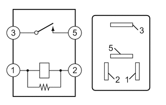
Measure the resistance according to the value(s) in the table below.
- Standard Resistance:
Tester Connection Condition Specified Condition 3 - 5 Auxiliary battery voltage applied between terminals 1 and 2 Below 1 Ω 3 - 5 Auxiliary battery voltage not applied between terminals 10 kΩ or higher
- Result:
Proceed to OK NG
OK
NG
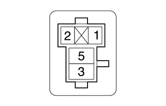
| *a | S/HTR FR Relay Holder |
Measure the voltage according to the value(s) in the table below.
- Standard Voltage:
Tester Connection Condition Specified Condition S/HTR FR relay holder terminal 1 - Body ground Ignition switch ON 11 V to 14 V S/HTR FR relay holder terminal 5 - Body ground Ignition switch off*1
Always*211 V to 14 V
*1: for HV Model
*2: for Gasoline Model
- Result:
Proceed to OK NG
OK
NG
Disconnect the U39 seat cushion climate control blower LH connector.
Disconnect the U7 seat cushion climate control blower RH connector.
Measure the resistance according to the value(s) in the table below.
- Standard Resistance:
Tester Connection Condition Specified Condition Click Location & Routing(U7,U39)Location & Routingewd_type=routing;type=c,c;code=U7,U39
Click Connector(U7)Seat>Front Seat Wire RH / Front Seat Wire LH>Seat Cushion Climate Control Blower Assembly RHewd_type=component;type=c;code=U7;pinno=1
Click Connector(U39)Seat>Front Seat Wire RH / Front Seat Wire LH>Seat Cushion Climate Control Blower Assembly LHewd_type=component;type=c;code=U39;pinno=1
S/HTR FR relay holder terminal 3 - U7-1 (+BAT) or U39-1 (IG) Always Below 1 Ω S/HTR FR relay holder terminal 3, U7-1 (+BAT) or U39-1 (IG) - Body ground Always 10 kΩ or higher
- Result:
Proceed to OK NG
OK
NG
Measure the resistance according to the value(s) in the table below.
- Standard Resistance:
Tester Connection Condition Specified Condition S/HTR FR relay holder terminal 2 - Body ground Always Below 1 Ω
- Result:
Proceed to OK NG
OK
NG
Temporarily replace the climate control switch (refreshing seat switch) with a new or known good one.
Click hereVehicle Interior>SEAT>SEAT HEATER SWITCH>REMOVAL202111,999999,_58,_111839,_0500783,RM100000001Z3FF,
- Result:
Proceed to NEXT
NEXT
Check the climate control seat operation.
- OK:
The climate control seat operates normally.
- Result:
Proceed to OK NG
OK
NG