DOOR / HATCH FUEL LID OPENER SYSTEM Fuel Lid Opener does not Operate
DESCRIPTION
When the fuel lid opener switch is pushed, a fuel lid opener switch signal is sent to the ECM. The ECM turns on the FUEL OPN relay and EFI-MAIN NO. 1 relay, and the fuel lid lock with motor assembly opens the fuel lid. When the fuel lid is open, a fuel lid courtesy switch signal is output from the fuel lid lock with motor assembly.
WIRING DIAGRAM
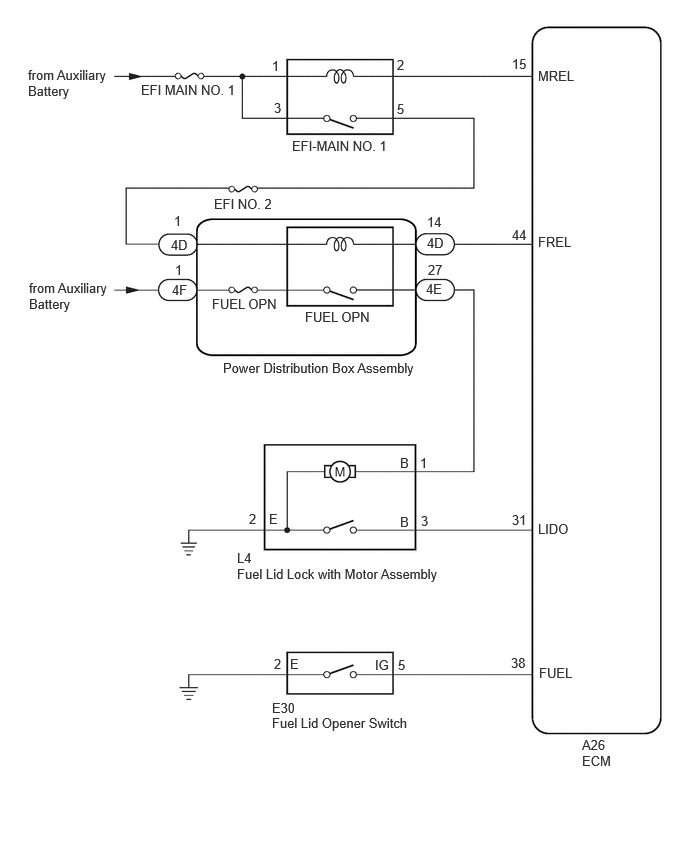
CAUTION / NOTICE / HINT
- NOTICE:
-
Inspect the fuses for circuits related to this system before performing the following procedure.
PROCEDURE
Check DTCs. (Health check)
- Result:
Result Proceed to No DTCs are output. A DTCs are output. B
A
B
Perform the Evaporative System Check using the GTS (Automatic Mode). Refer to "CONFIRMATION DRIVING PATTERN" of P045011.
Check for DTCs.
- Powertrain > Engine > Trouble Codes
- 50001 372
- OK:
Evaporative emission control system DTCs are not output.
- Result:
Proceed to OK NG
OK
NG
Perform the Active Test according to the display on the GTS.
- Powertrain > Engine > Active Test
-
Tester Display Measurement Item Control Range Diagnostic Note Activate the Fuel Filler Opener Fuel lid lock with motor assembly OFF/ON -
- Powertrain > Engine > Active Test
-
Tester Display Activate the Fuel Filler Opener - 50004 372 41
- OK:
The fuel lid lock with motor assembly operates normally.
- Result:
Proceed to OK NG
OK
NG
Read the Data List according to the display on the GTS.
- Powertrain > Engine > Data List
-
Tester Display Measurement Item Range Normal Condition Diagnostic Note Fuel Lid SW Fuel lid opener switch status Close or Open Close: Fuel lid opener switch not pushed
Open: Fuel lid opener switch pushed-
- Powertrain > Engine > Data List
-
Tester Display Fuel Lid SW - 50003 372 37
- OK:
The GTS display changes correctly in response to the operation of the fuel lid opener switch.
- Result:
Proceed to OK NG
OK
NG
Read the Data List according to the display on the GTS.
- Powertrain > Engine > Data List
-
Tester Display Measurement Item Range Normal Condition Diagnostic Note Fuel Lid Sensor SW Fuel lid courtesy switch status Close or Open Close: Fuel lid closed
Open: Fuel lid open-
- Powertrain > Engine > Data List
-
Tester Display Fuel Lid Sensor SW - 50003 372 38
- OK:
The GTS display changes correctly in response to the operation of the fuel lid courtesy switch (fuel lid lock with motor assembly).
- Result:
Proceed to OK NG
OK
NG
- Result:
Proceed to OK NG
OK
NG
Disconnect the A26 ECM connector.
Measure the resistance according to the value(s) in the table below.
- Standard Resistance:
Tester Connection Condition Specified Condition Click Location & Routing(L4,A26)Location & Routingewd_type=routing;type=c,c;code=L4,A26
Click Connector(L4)Body>No. 2 Floor Wire>Fuel Lid Lock with Motor Assemblyewd_type=component;type=c;code=L4;pinno=3
Click Connector(A26)Engine Compartment>Engine Room Main Wire / Transmission Wire>ECMewd_type=component;type=c;code=A26;pinno=31
L4-3 (B) - A26-31 (LIDO) Always Below 1 Ω L4-3 (B) or A26-31 (LIDO) - Body ground Always 10 kΩ or higher
- Result:
Proceed to OK NG
OK
NG
- Result:
Proceed to OK NG
OK
NG
Disconnect the A26 ECM connector.
Measure the resistance according to the value(s) in the table below.
- Standard Resistance:
Tester Connection Condition Specified Condition Click Location & Routing(E30,A26)Location & Routingewd_type=routing;type=c,c;code=E30,A26
Click Connector(E30)Instrument Panel>Instrument Panel Wire / Radio Wiring Sub-Assy / Telephone Computer Wire>Fuel Lid Opener Switchewd_type=component;type=c;code=E30;pinno=5,2
Click Connector(A26)Engine Compartment>Engine Room Main Wire / Transmission Wire>ECMewd_type=component;type=c;code=A26;pinno=38
E30-5 (IG) - A26-38 (FUEL) Always Below 1 Ω E30-2 (E) - Body ground Always Below 1 Ω E30-5 (IG) or A26-38 (FUEL) - Body ground Always 10 kΩ or higher
- Result:
Proceed to OK NG
OK
NG
- Result:
Proceed to OK NG
OK
NG
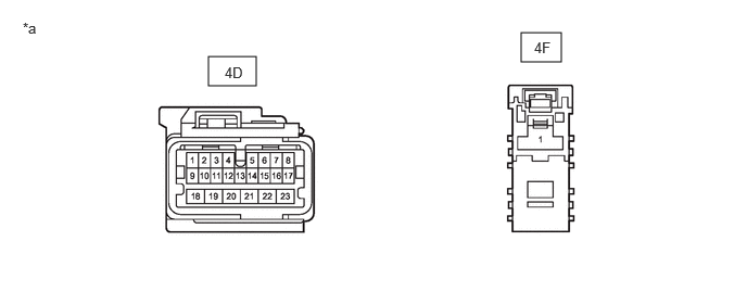
| *a | Front view of wire harness connector (to Power Distribution Box Assembly) | - | - |
Disconnect the 4D and 4F power distribution box assembly connectors.
Measure the voltage according to the value(s) in the table below.
- Standard Voltage:
Tester Connection Condition Specified Condition 4F-1 - Body ground Ignition switch off 11 to 14 V 4D-1 - Body ground Ignition switch ON 11 to 14 V Ignition switch off and fuel lid opener switch not pressed → fuel lid opener switch pressed Below 1 V → 11 to 14 V
- Result:
Result Proceed to OK A The result for terminal 4F-1 is not as specified. B The result for terminal 4D-1 (with ignition switch ON) is not as specified. The result for terminal 4D-1 (with ignition switch off and fuel lid opener switch pressed) is not as specified. C
A
B
C
Disconnect the A26 ECM connector.
Measure the resistance according to the value(s) in the table below.
- Standard Resistance:
Tester Connection Condition Specified Condition Click Location & Routing(A26)Location & Routingewd_type=routing;type=c;code=A26
Click Connector(A26)Engine Compartment>Engine Room Main Wire / Transmission Wire>ECMewd_type=component;type=c;code=A26;pinno=44
4D-14 - A26-44 (FREL) Always Below 1 Ω 4D-14 or A26-44 (FREL) - Body ground Always 10 kΩ or higher
- Result:
Proceed to OK NG
OK
NG
Measure the resistance according to the value(s) in the table below.
- Standard Resistance:
Tester Connection Condition Specified Condition Click Location & Routing(L4)Location & Routingewd_type=routing;type=c;code=L4
Click Connector(L4)Body>No. 2 Floor Wire>Fuel Lid Lock with Motor Assemblyewd_type=component;type=c;code=L4;pinno=1
4E-27 - L4-1 (B) Always Below 1 Ω 4E-27 or L4-1 (B) - Body ground Always 10 kΩ or higher
- Result:
Proceed to OK NG
OK
NG
Replace the power distribution box assembly.
- Result:
Proceed to NEXT
NEXT
Check that the fuel lid can be opened.
- OK:
The fuel lid can be opened.
- Result:
Proceed to OK NG
OK
NG