RM38N0EC
_59
Vehicle Exterior
_111831
DOOR / HATCH
_0501473
FUEL LID OPENER MOTOR ASSEMBLY
G
DOOR / HATCH FUEL LID OPENER MOTOR ASSEMBLY INSPECTION
PROCEDURE

 77030A
1.INSPECT FUEL LID LOCK WITH MOTOR ASSEMBLY
77030A
1.INSPECT FUEL LID LOCK WITH MOTOR ASSEMBLY
a.
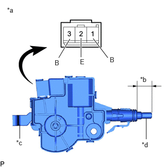
Check the operation of the fuel lid lock with motor assembly (motor operation).
i.
3.01,2.865 3.01,2.438
false
1.667,1.177 1.667,0.781
true
2.219,1.188 1.917,0.792
true
0.406,2.854 0.406,2.563
false
1.208,1.188 1.438,0.802
true
0.146,0.125 0.458,0.323
0.313,0.198
10
false
*a
2.917,2.896 3.229,3.094
0.313,0.198
10
false
*d
1.646,1.188 1.802,1.385
0.156,0.198
10
false
E
2.26,1.146 2.417,1.344
0.156,0.198
10
false
B
2.885,1.552 3.198,1.75
0.313,0.198
10
false
*b
0.333,2.854 0.646,3.052
0.313,0.198
10
false
*c
1.125,1.208 1.281,1.406
0.156,0.198
10
false
B
| *a | Component without harness connected
(Fuel Lid Lock with Motor Assembly) |
| *b | Shaft Stroke |
| *c | Lever |
| *d | Shaft |
Apply auxiliary battery voltage to the fuel lid lock with motor assembly connector, and check that the fuel lid lock with motor assembly operates smoothly.
- OK:
Auxiliary Battery Connection Specified Condition Auxiliary battery positive (+) → Terminal 1 (B)
Auxiliary battery negative (-) → Terminal 2 (E)16.2 to 17.4 mm
(0.638 to 0.685 in.)
If the result is not as specified, replace the fuel lid lock with motor assembly.
b.
Check the operation of the fuel lid lock with motor assembly (fuel lid courtesy switch).
i.
Measure the resistance according the value(s) in the table below.
- Standard Resistance:
Tester Connection Condition Specified Condition 2 (E) - 3 (B) Not pushed (ON) Below 7.5 Ω 2 (E) - 3 (B) Pushed (OFF) 50 MΩ or higher
If the result is not as specified, replace the fuel lid lock with motor assembly.
c.
Measure the shaft stroke.
- OK:
Area Condition Specified Condition Shaft stroke Lever pulled 18.3 mm
(0.720 in.)
If the result is not as specified, replace the fuel lid lock with motor assembly.