MIRROR (EXT) POWER MIRROR CONTROL SYSTEM(w/ Memory) Front Passenger Side Power Mirror cannot be Adjusted with Power Mirror Switch
DESCRIPTION
The outer mirror switch assembly sends the mirror adjust switch signals to the main body ECU (multiplex network body ECU). The main body ECU (multiplex network body ECU) then sends the received mirror adjust switch signals to the outer mirror control ECU assembly (front passenger door) via CAN communication. On receiving the signal, the outer mirror control ECU assembly (front passenger door) operates the vertical and horizontal mirror motors, which are built into the outer rear view mirror assembly (front passenger door), to adjust the mirror surface position.
WIRING DIAGRAM
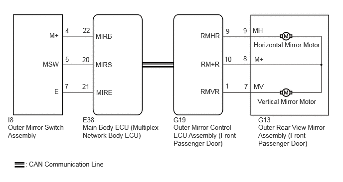
CAUTION / NOTICE / HINT
- NOTICE:
- ·
The power mirror control system (w/ Memory) uses the CAN communication system. Inspect the communication functions by following How to Proceed with Troubleshooting. Troubleshoot the power mirror control system (w/ Memory) after confirming that the communication systems are functioning properly.
·Before replacing the main body ECU (multiplex network body ECU), refer to Service Bulletin.
PROCEDURE
- Result:
Proceed to OK NG
OK
NG
Disconnect the G13 outer rear view mirror assembly (front passenger door).
Disconnect the G19 outer mirror control ECU assembly (front passenger door).
Measure the resistance according to the value(s) in the table below.
- Standard Resistance:
Tester Connection Condition Specified Condition Click Location & Routing(G13,G19)Location & Routingewd_type=routing;type=c,c;code=G13,G19
Click Connector(G13)Body>Front Door Wire RH / Front Door Wire LH>Outer Rear View Mirror Assembly RHewd_type=component;type=c;code=G13;pinno=7,9,8
Click Connector(G19)Body>Front Door Wire RH / Front Door Wire LH>Outer Mirror Control ECU Assembly RHewd_type=component;type=c;code=G19;pinno=1,9,10
G13-7 (MV) - G19-1 (RMVR) Always Below 1 Ω G13-9 (MH) - G19-9 (RMHR) Always Below 1 Ω G13-8 (M+) - G19-10 (RM+R) Always Below 1 Ω G13-7 (MV) or G19-1 (RMVR) - Body ground Always 10 kΩ or higher G13-9 (MH) or G19-9 (RMHR) - Body ground Always 10 kΩ or higher G13-8 (M+) or G19-10 (RM+R) - Body ground Always 10 kΩ or higher
- Result:
Proceed to OK NG
OK
NG
- Result:
Proceed to OK NG
OK
NG
Disconnect the E38 main body ECU (multiplex network body ECU).
Measure the resistance according to the value(s) in the table below.
- Standard Resistance:
Tester Connection Condition Specified Condition Click Location & Routing(I8,E38)Location & Routingewd_type=routing;type=c,c;code=I8,E38
Click Connector(I8)Body>No. 2 Front Door Wire RH / No. 2 Front Door Wire LH>Outer Mirror Switch Assemblyewd_type=component;type=c;code=I8;pinno=7,4,5
Click Connector(E38)Instrument Panel>Instrument Panel Wire / Telephone Computer Wire>Multiplex Network Body ECUewd_type=component;type=c;code=E38;pinno=21,22,20
I8-7 (E) - E38-21 (MIRE) Always Below 1 Ω I8-4 (M+) - E38-22 (MIRB) Always Below 1 Ω I8-5 (MSW) - E38-20 (MIRS) Always Below 1 Ω I8-7 (E) or E38-21 (MIRE) - Body ground Always 10 kΩ or higher I8-4 (M+) or E38-22 (MIRB) - Body ground Always 10 kΩ or higher I8-5 (MSW) or E38-20 (MIRS) - Body ground Always 10 kΩ or higher
- Result:
Proceed to OK NG
OK
NG
Temporarily replace the outer mirror control ECU assembly with a normally functioning one.
- HINT:
- Result:
Proceed to NEXT
NEXT
Check the power mirror control system.
- Result:
Result Proceed to Power mirror control function operates normally A Power mirror control function does not operate normally B
A
B