THEFT DETERRENT / KEYLESS ENTRY SMART ENTRY AND START SYSTEM(for Entry Function, Gasoline Model) TERMINALS OF ECU
CHECK CERTIFICATION ECU (SMART KEY ECU ASSEMBLY)
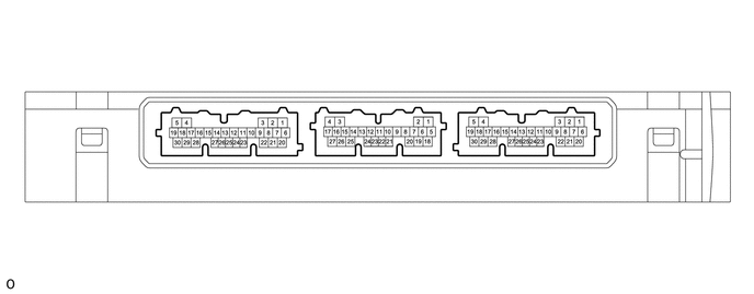
Disconnect the A15 and E52 certification ECU (smart key ECU assembly) connectors.
Measure the voltage and resistance according to the value(s) in the table below.
| Tester Connection | Terminal Description | Condition | Specified Condition | Related Data List Item |
|---|---|---|---|---|
| E52-29 (E) - Body ground | Ground | Always | Below 1 Ω | - |
| E52-6 (+B) - E52-29 (E) | Power supply | Always | 11 to 14 V | - |
| A15-22 (CUTB) - E52-29 (E) | Dark current cut pin* | Always | 11 to 14 V | - |
*: In order to prevent the vehicle auxiliary battery from being depleted when the vehicle is shipped long distances, a fuse that cuts unnecessary electrical load while the vehicle is being shipped is installed in the circuit. If the fuse is removed, the circuit becomes open. If the fuse that is between the vehicle auxiliary battery and terminal CUTB is removed and the circuit is open, the certification ECU (smart key ECU assembly) changes to a certain control mode (example: the transmission of radio waves every 0.25 seconds, which form the detection area, stops).
Reconnect the A15 and E52 certification ECU (smart key ECU assembly) connectors.
Measure the voltage and check for pulses according to the value(s) in the table below.
| Tester Connection | Terminal Description | Condition | Specified Condition | Related Data List Item |
|---|---|---|---|---|
| A15-24 (IGPD) - E52-29 (E) | IG power supply | Ignition switch off → ON | Below 1 V → 9 V or higher | Power source control
IGP Relay Circuit (Outside) Monitor |
| A15-11 (IGRD) - E52-29 (E) | IG power supply | Ignition switch off → ON | Below 1 V → 9 V or higher | Power source control
IGR Relay Circuit (Outside) Monitor |
| E52-21 (ACCD) - E52-29 (E) | ACC power supply | Ignition switch off → ACC | Below 1 V → 8.5 V or higher | Power source control
ACC Relay Monitor |
| E52-16 (CLG1) - E52-29 (E) | Output to driver door electrical key antenna
(request signal (challenge) is sent to door electrical key antenna from certification ECU (smart key ECU assembly) to form detection area) |
Procedure:
1.
Ignition switch off 2.
All doors closed 3.
Electrical key transmitter sub-assembly not inside vehicle 4.
All doors locked through wireless operation (electrical key transmitter sub-assembly brought inside detection area*) |
Pulse generation
(See waveform 1) |
- |
| Procedure:
1.
Ignition switch off 2.
All doors closed 3.
Electrical key transmitter sub-assembly not inside vehicle 4.
All doors locked through wireless operation (electrical key transmitter sub-assembly brought outside detection area*) |
Pulse generation
(See waveform 2) |
- | ||
| E52-16 (CLG1) - E52-29 (E) | Input to driver door lock sensor
(front door outside handle assembly (for driver door) lock sensor on signal is sent to the certification ECU (smart key ECU assembly)) |
Procedure:
1.
Ignition switch off 2.
Electrical key transmitter sub-assembly brought outside vehicle 3.
All doors closed 4.
All doors locked through wireless operation (electrical key transmitter sub-assembly brought outside detection area*) 5.
Driver door lock sensor touched |
Pulse generation
(See waveform 3) |
Entry&Start
Driver Side Lock Sensor |
| E52-16 (CLG1) - E52-29 (E) | Input to driver door unlock sensor
(when system is in unlock standby mode and unlock sensor is touched, door electrical key antenna sends unlock sensor input signal (sensing) to certification ECU (smart key ECU assembly)) |
Procedure:
1.
Ignition switch off 2.
Electrical key transmitter sub-assembly brought outside vehicle 3.
All doors locked 4.
Electrical key transmitter sub-assembly not near the vehicle 5.
Driver door unlock sensor touched |
Pulse generation
(See waveform 4) |
Entry&Start
Driver Side Unlock Sensor |
| E52-15 (CG1B) - E52-29 (E) | Output to driver door electrical key antenna (terminal on opposite side of component from CLG1 output terminal) | Procedure:
1.
Ignition switch off 2.
All doors closed 3.
Electrical key transmitter sub-assembly not inside vehicle 4.
All doors locked through wireless operation (electrical key transmitter sub-assembly brought inside detection area*) |
Pulse generation
(See waveform 5) |
- |
| Procedure:
1.
Ignition switch off 2.
All doors closed 3.
Electrical key transmitter sub-assembly not inside vehicle 4.
All doors locked through wireless operation (electrical key transmitter sub-assembly brought outside detection area*) |
Pulse generation
(See waveform 6) |
- | ||
| E52-10 (CLG2) - E52-29 (E) | Output to front passenger door electrical key antenna
(request signal (challenge) is sent to door electrical key antenna from certification ECU (smart key ECU assembly) to form detection area) |
Procedure:
1.
Ignition switch off 2.
All doors closed 3.
Electrical key transmitter sub-assembly not inside vehicle 4.
All doors locked through wireless operation (electrical key transmitter sub-assembly brought inside detection area*) |
Pulse generation
(See waveform 1) |
- |
| Procedure:
1.
Ignition switch off 2.
All doors closed 3.
Electrical key transmitter sub-assembly not inside vehicle 4.
All doors locked through wireless operation (electrical key transmitter sub-assembly brought outside detection area*) |
Pulse generation
(See waveform 2) |
- | ||
| E52-10 (CLG2) - E52-29 (E) | Input to front passenger door lock sensor
(front door outside handle assembly (for front passenger door) lock sensor on signal is sent to the certification ECU (smart key ECU assembly)) |
Procedure:
1.
Ignition switch off 2.
Electrical key transmitter sub-assembly brought outside vehicle 3.
All doors closed 4.
All doors locked through wireless operation (electrical key transmitter sub-assembly brought outside detection area*) 5.
Front passenger door lock sensor touched |
Pulse generation
(See waveform 3) |
Entry&Start
Passenger Side Lock Sensor |
| E52-10 (CLG2) - E52-29 (E) | Input to front passenger door unlock sensor
(when system is in unlock standby mode and unlock sensor is touched, door electrical key antenna sends unlock sensor input signal (sensing) to certification ECU (smart key ECU assembly)) |
Procedure:
1.
Ignition switch off 2.
Electrical key transmitter sub-assembly brought outside vehicle 3.
All doors locked 4.
Electrical key transmitter sub-assembly not near the vehicle 5.
Front passenger door unlock sensor touched |
Pulse generation
(See waveform 4) |
Entry&Start
Passenger Side Unlock Sensor |
| E52-9 (CG2B) - E52-29 (E) | Output to front passenger door electrical key antenna (terminal on opposite side of component from CLG2 output terminal) | Procedure:
1.
Ignition switch off 2.
All doors closed 3.
Electrical key transmitter sub-assembly not inside vehicle 4.
All doors locked through wireless operation (electrical key transmitter sub-assembly brought inside detection area*) |
Pulse generation
(See waveform 5) |
- |
| Procedure:
1.
Ignition switch off 2.
All doors closed 3.
Electrical key transmitter sub-assembly not inside vehicle 4.
All doors locked through wireless operation (electrical key transmitter sub-assembly brought outside detection area*) |
Pulse generation
(See waveform 6) |
- | ||
| K6-4 (CLG8) - E52-29 (E) | Output to electrical key antenna (outside luggage compartment) | Procedure:
1.
Ignition switch off 2.
Electrical key transmitter sub-assembly brought outside vehicle 3.
All doors closed 4.
License plate light assembly with back door opener switch off → on |
Pulse generation
(See waveform 7) |
- |
| K6-3 (CG8B) - E52-29 (E) | Output to electrical key antenna (outside luggage compartment) (terminal on opposite side of component from CLG8 output terminal) | Procedure:
1.
Ignition switch off 2.
Electrical key transmitter sub-assembly brought outside vehicle 3.
All doors closed 4.
License plate light assembly with back door opener switch off → on |
Pulse generation
(See waveform 8) |
- |
| K6-16 (TSW5) - E52-29 (E) | License plate light assembly with back door opener switch (open switch) signal input | License plate light assembly with back door opener switch (open switch) off → on | Pulse generation
(See waveform 9) |
Entry&Start
Trunk Lid/Back Door Unlock Switch |
| K6-17 (TSW6) - E52-29 (E) | License plate light assembly with back door opener switch (lock switch) signal input | License plate light assembly with back door opener switch (lock switch) off → on | Pulse generation
(See waveform 9) |
Entry&Start
Trunk Lid/Back Door Lock Switch |
| K6-21 (RCO) - E52-29 (E) | Output to electrical key and tire pressure warning ECU and receiver
(Power supply for electrical key and tire pressure warning ECU and receiver. Certification ECU (smart key ECU assembly) outputs 5 V when receiver starts operating.) |
Procedure:
1.
Ignition switch off 2.
Electrical key transmitter sub-assembly brought outside detection area but kept inside wireless function operational area 3.
Lock or unlock switch of electrical key transmitter sub-assembly not pressed → pressed |
Pulse generation
(See waveform 10) |
- |
| K6-11 (RDAM) - E52-29 (E) | Electrical key and tire pressure warning ECU and receiver verifies data received from electrical key transmitter sub-assembly.
Electrical key and tire pressure warning ECU and receiver sends data from electrical key transmitter sub-assembly to certification ECU (smart key ECU assembly) (Electrical key and tire pressure warning ECU and receiver intermittently grounds 12 V signal from certification ECU (smart key ECU assembly)). |
Proceed:
1.
Ignition switch off 2.
All doors locked 3.
Electrical key transmitter sub-assembly not inside vehicle 4.
Electrical key transmitter sub-assembly brought outside detection area but kept inside wireless function operational area 5.
Lock or unlock switch of electrical key transmitter sub-assembly not pressed → pressed |
Pulse generation
(See waveform 11) |
- |
| K6-12 (CSEL) - E52-29 (E) | Communication channel switching circuit | Procedure:
1.
Ignition switch off 2.
All doors closed |
Below 1 V → Pulse generation | - |
*: For details about the entry function detection area, refer to Operation Check.
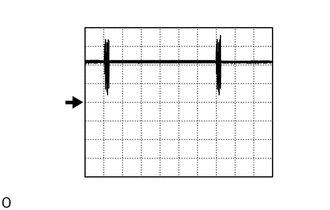
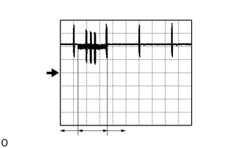
Using an oscilloscope, check waveform 1.
- NOTICE:
-
The oscilloscope waveform shown in the illustration is an example for reference only. Noise, chattering, etc. are not shown.
| Item | Content |
|---|---|
| Tester Connection | E52-16 (CLG1) - E52-29 (E)
E52-10 (CLG2) - E52-29 (E) |
| Tool Setting | 5 V/DIV., 500 ms./DIV. |
| Condition | Procedure:
1.
Ignition switch off 2.
All doors closed 3.
Electrical key transmitter sub-assembly not inside vehicle 4.
All doors locked through wireless operation (electrical key transmitter sub-assembly brought inside detection area*) |
*: For details about the entry function detection area, refer to Operation Check.
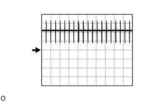
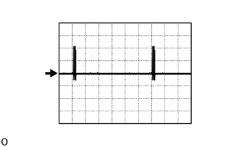
Using an oscilloscope, check waveform 2.
- NOTICE:
-
The oscilloscope waveform shown in the illustration is an example for reference only. Noise, chattering, etc. are not shown.
| Item | Content |
|---|---|
| Tester Connection | E52-16 (CLG1) - E52-29 (E)
E52-10 (CLG2) - E52-29 (E) |
| Tool Setting | 5 V/DIV., 500 ms./DIV. |
| Condition | Procedure:
1.
Ignition switch off 2.
All doors closed 3.
Electrical key transmitter sub-assembly not inside vehicle 4.
All doors locked through wireless operation (electrical key transmitter sub-assembly brought outside detection area*) |
*: For details about the entry function detection area, refer to Operation Check.
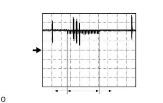
| *a | Lock sensor not touched |
| *b | Lock sensor touched |
Using an oscilloscope, check waveform 3.
- NOTICE:
-
The oscilloscope waveform shown in the illustration is an example for reference only. Noise, chattering, etc. are not shown.
| Item | Content |
|---|---|
| Tester Connection | E52-16 (CLG1) - E52-29 (E) |
| Tool Setting | 5 V/DIV., 100 ms./DIV. |
| Condition | Procedure:
1.
Ignition switch off 2.
Electrical key transmitter sub-assembly brought outside vehicle 3.
All doors closed 4.
All doors locked through wireless operation (electrical key transmitter sub-assembly brought outside detection area*) 5.
Driver door lock sensor not touched → touched |
| Item | Content |
|---|---|
| Tester Connection | E52-10 (CLG2) - E52-29 (E) |
| Tool Setting | 5 V/DIV., 100 ms./DIV. |
| Condition | Procedure:
1.
Ignition switch off 2.
Electrical key transmitter sub-assembly brought outside vehicle 3.
All doors closed 4.
All doors locked through wireless operation (electrical key transmitter sub-assembly brought outside detection area*) 5.
Front passenger door lock sensor not touched → touched |
*: For details about the entry function detection area, refer to Operation Check.
| *a | Unlock sensor not touched |
| *b | Unlock sensor touched |
Using an oscilloscope, check waveform 4.
- NOTICE:
-
The oscilloscope waveform shown in the illustration is an example for reference only. Noise, chattering, etc. are not shown.
| Item | Content |
|---|---|
| Tester Connection | E52-16 (CLG1) - E52-29 (E) |
| Tool Setting | 5 V/DIV., 100 ms./DIV. |
| Condition | Procedure:
1.
Ignition switch off 2.
Electrical key transmitter sub-assembly brought outside vehicle 3.
All doors locked 4.
Electrical key transmitter sub-assembly not near the vehicle 5.
Driver door unlock sensor not touched → touched |
| Item | Content |
|---|---|
| Tester Connection | E52-10 (CLG2) - E52-29 (E) |
| Tool Setting | 5 V/DIV., 100 ms./DIV. |
| Condition | Procedure:
1.
Ignition switch off 2.
Electrical key transmitter sub-assembly brought outside vehicle 3.
All doors locked 4.
Electrical key transmitter sub-assembly not near the vehicle 5.
Front passenger door unlock sensor not touched → touched |
Using an oscilloscope, check waveform 5.
- NOTICE:
-
The oscilloscope waveform shown in the illustration is an example for reference only. Noise, chattering, etc. are not shown.
| Item | Content |
|---|---|
| Tester Connection | E52-15 (CG1B) - E52-29 (E)
E52-9 (CG2B) - E52-29 (E) |
| Tool Setting | 5 V/DIV., 500 ms./DIV. |
| Condition | Procedure:
1.
Ignition switch off 2.
All doors closed 3.
Electrical key transmitter sub-assembly not inside vehicle 4.
All doors locked through wireless operation (electrical key transmitter sub-assembly brought inside detection area*) |
*: For details about the entry function detection area, refer to Operation Check.
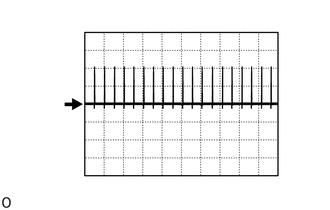
Using an oscilloscope, check waveform 6.
- NOTICE:
-
The oscilloscope waveform shown in the illustration is an example for reference only. Noise, chattering, etc. are not shown.
| Item | Content |
|---|---|
| Tester Connection | E52-15 (CG1B) - E52-29 (E)
E52-9 (CG2B) - E52-29 (E) |
| Tool Setting | 5 V/DIV., 500 ms./DIV. |
| Condition | Procedure:
1.
Ignition switch off 2.
All doors closed 3.
Electrical key transmitter sub-assembly not inside vehicle 4.
All doors locked through wireless operation (electrical key transmitter sub-assembly brought outside detection area*) |
*: For details about the entry function detection area, refer to Operation Check.
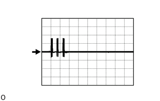
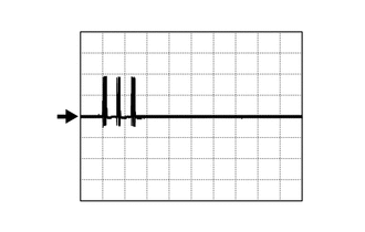
Using an oscilloscope, check waveform 7.
- NOTICE:
-
The oscilloscope waveform shown in the illustration is an example for reference only. Noise, chattering, etc. are not shown.
| Item | Content |
|---|---|
| Tester Connection | K6-4 (CLG8) - E52-29 (E) |
| Tool Setting | 5 V/DIV., 50 ms./DIV. |
| Condition | Procedure:
1.
Ignition switch off 2.
Electrical key transmitter sub-assembly brought outside vehicle 3.
All doors closed 4.
License plate light assembly with back door opener switch off → on |
Using an oscilloscope, check waveform 8.
- NOTICE:
-
The oscilloscope waveform shown in the illustration is an example for reference only. Noise, chattering, etc. are not shown.
| Item | Content |
|---|---|
| Tester Connection | K6-3 (CG8B) - E52-29 (E) |
| Tool Setting | 5 V/DIV., 50 ms./DIV. |
| Condition | Procedure:
1.
Ignition switch off 2.
Electrical key transmitter sub-assembly brought outside vehicle 3.
All doors closed 4.
License plate light assembly with back door opener switch off → on |
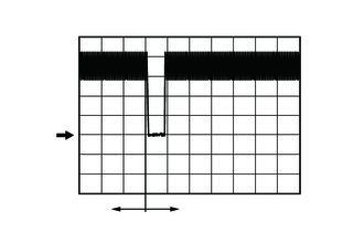
| *a | Checking for switch on signal at short intervals |
| *b | Before license plate light assembly with back door opener switch pressed |
| *c | After license plate light assembly with back door opener switch pressed |
Using an oscilloscope, check waveform 9.
- NOTICE:
-
The oscilloscope waveform shown in the illustration is an example for reference only. Noise, chattering, etc. are not shown.
| Item | Content |
|---|---|
| Tester Connection | K6-16 (TSW5) - E52-29 (E) |
| Tool Setting | 2 V/DIV., 500 ms./DIV. |
| Condition | License plate light assembly with back door opener switch (open switch) off → on |
| Item | Content |
|---|---|
| Tester Connection | K6-17 (TSW6) - E52-29 (E) |
| Tool Setting | 2 V/DIV., 500 ms./DIV. |
| Condition | License plate light assembly with back door opener switch (lock switch) off → on |
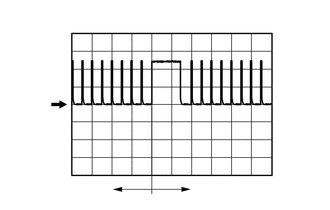
| *a | Before lock or unlock switch of electrical key transmitter sub-assembly pressed |
| *b | After lock or unlock switch of electrical key transmitter sub-assembly pressed |
Using an oscilloscope, check waveform 10.
- NOTICE:
-
The oscilloscope waveform shown in the illustration is an example for reference only. Noise, chattering, etc. are not shown.
| Item | Content |
|---|---|
| Tester Connection | K6-21 (RCO) - E52-29 (E) |
| Tool Setting | 2 V/DIV., 500 ms./DIV. |
| Condition | Procedure:
1.
Ignition switch off 2.
Electrical key transmitter sub-assembly brought outside detection area but kept inside wireless function operational area 3.
Lock or unlock switch of electrical key transmitter sub-assembly not pressed → pressed |
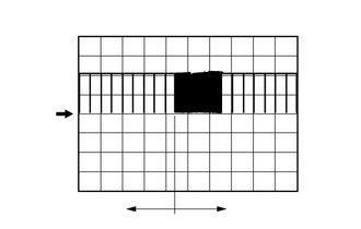
| *a | Before lock or unlock switch of electrical key transmitter sub-assembly pressed |
| *b | After lock or unlock switch of electrical key transmitter sub-assembly pressed |
Using an oscilloscope, check waveform 11.
- NOTICE:
-
The oscilloscope waveform shown in the illustration is an example for reference only. Noise, chattering, etc. are not shown.
| Item | Content |
|---|---|
| Tester Connection | K6-11 (RDAM) - E52-29 (E) |
| Tool Setting | 5 V/DIV., 500 ms./DIV. |
| Condition | Procedure:
1.
Ignition switch off 2.
All doors locked 3.
Electrical key transmitter sub-assembly not inside vehicle 4.
Electrical key transmitter sub-assembly brought outside detection area but kept inside wireless function operational area 5.
Lock or unlock switch of electrical key transmitter sub-assembly not pressed → pressed |
CHECK POWER DISTRIBUTION BOX ASSEMBLY AND MAIN BODY ECU (MULTIPLEX NETWORK BODY ECU)
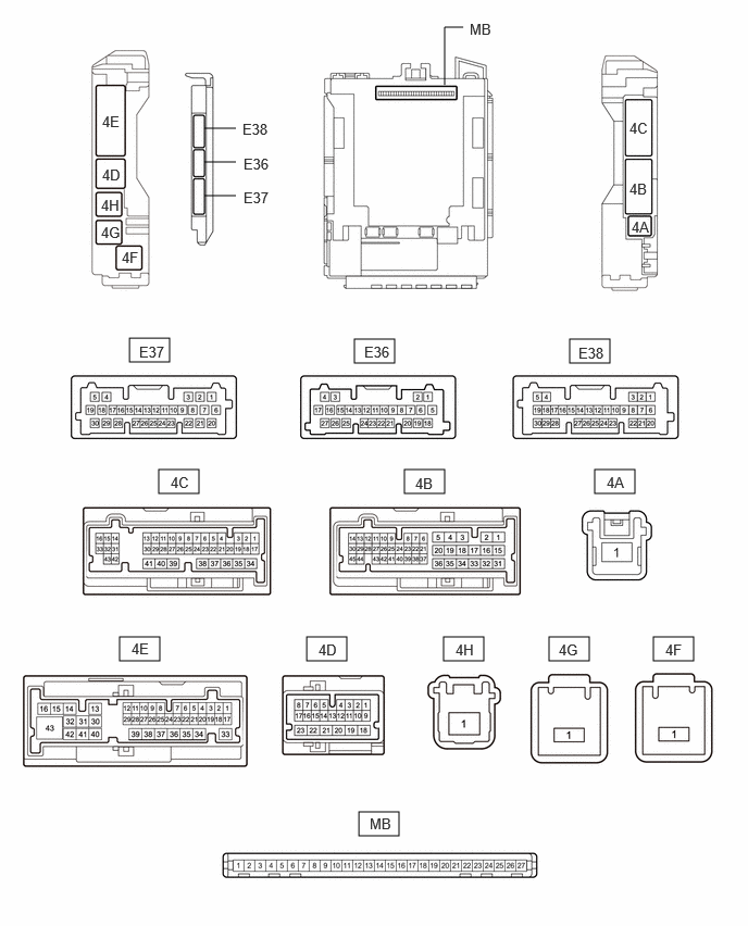
Remove the main body ECU (multiplex network body ECU) from the power distribution box assembly.
Measure the voltage and resistance according to the value(s) in the table below.
| Tester Connection | Terminal Description | Condition | Specified Condition |
|---|---|---|---|
| MB-13 (GND1) - Body ground | Ground | Always | Below 1 Ω |
| MB-26 (BECU) - Body ground | Auxiliary battery power supply (for CPU) | Always | 11 to 14 V |
SMART ENTRY AND START SYSTEM (for Start Function)
POWER DOOR LOCK CONTROL SYSTEM
WIRELESS DOOR LOCK CONTROL SYSTEM
POWER BACK DOOR SYSTEM (w/ Power Back Door System)