LIGHTING (EXT) LIGHTING SYSTEM Taillight Relay Circuit
DESCRIPTION
The main body ECU (multiplex network body ECU) controls the operation of the TAIL relay.
WIRING DIAGRAM

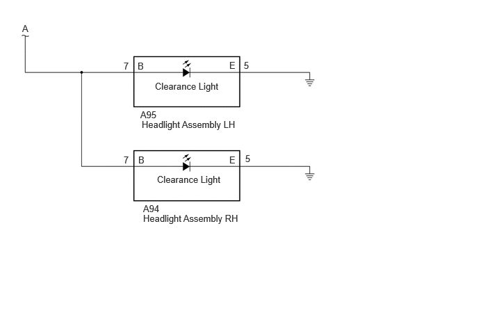
CAUTION / NOTICE / HINT
- NOTICE:
- ·
Inspect the fuses for circuits related to this system before performing the following procedure.
·If the main body ECU (multiplex network body ECU) is replaced, refer to Service Bulletin.
·First perform the communication function inspections in How to Proceed with Troubleshooting to confirm that there are no CXPI communication malfunctions before troubleshooting this symptom.
PROCEDURE
Read the Data List according to the display on the GTS.
- Body Electrical > Power Distribution Box > Data List
-
Tester Display Measurement Item Normal Condition Reference Value Diagnostic Note Tail Light Input Signal Taillight input OFF or ON OFF: Taillights off
ON: Taillights on-
- Body Electrical > Power Distribution Box > Data List
-
Tester Display Tail Light Input Signal - 50003 475 1290
- OK:
Display changes according to the taillight illumination condition.
- Result:
Proceed to OK NG
OK
NG
Turn the light control switch to the TAIL position.
Read the Data List according to the display on the GTS.
- Body Electrical > Power Distribution Box > Data List
-
Tester Display Measurement Item Normal Condition Reference Value Diagnostic Note Tail Light Fuse Shut Off Status Taillight fuse shut off status OFF or ON OFF: Fuse has no shut off history
ON: Fuse has shut off history-
- Body Electrical > Power Distribution Box > Data List
-
Tester Display Tail Light Fuse Shut Off Status - 50003 475 1293
- OK:
The Data List value displays "OFF".
- Result:
Proceed to OK NG
OK
NG
Read the Data List according to the display on the GTS.
- Body Electrical > Power Distribution Box > Data List
-
Tester Display Measurement Item Normal Condition Reference Value Diagnostic Note Tail Light Output Signal Taillight output OFF or ON OFF: Taillights off
ON: Taillights on-
- Body Electrical > Power Distribution Box > Data List
-
Tester Display Tail Light Output Signal - 50003 475 1291
- OK:
Display changes according to the taillight illumination condition.
- Result:
Proceed to OK NG
OK
NG
Disconnect the 4G power distribution box assembly connector.
Measure the voltage according to the value(s) in the table below.
- Standard Voltage:
Tester Connection Condition Specified Condition 4G-1 - Body ground Ignition switch off 11 to 14 V
- Result:
Proceed to OK NG
OK
NG
Disconnect the L15 rear combination light assembly LH connector.
Disconnect the K15 rear combination light assembly RH connector.
Disconnect the a2 rear light assembly LH connector.
Disconnect the a1 rear light assembly RH connector.
Disconnect the T4 license plate light assembly with back door opener switch connector.
Disconnect the A95 headlight assembly LH connector.
Disconnect the A94 Headlight assembly RH connector.
Disconnect the 4E power distribution box assembly connector.
Measure the resistance according to the value(s) in the table below.
- Standard Resistance:
- Result:
Proceed to OK NG
OK
NG
Disconnect the L15 rear combination light assembly LH connector.
Turn the light control switch to the TAIL position.
Read the Data List according to the display on the GTS.
- Body Electrical > Power Distribution Box > Data List
-
Tester Display Measurement Item Normal Condition Reference Value Diagnostic Note Tail Light Fuse Shut Off Status Taillight fuse shut off status OFF or ON OFF: Fuse has no shut off history
ON: Fuse has shut off history-
- Body Electrical > Power Distribution Box > Data List
-
Tester Display Tail Light Fuse Shut Off Status - 50003 475 1293
- OK:
The Data List value displays "OFF".
- Result:
Proceed to OK NG
OK
NG
Disconnect the K15 rear combination light assembly RH connector.
Turn the light control switch to the TAIL position.
Read the Data List according to the display on the GTS.
- Body Electrical > Power Distribution Box > Data List
-
Tester Display Measurement Item Normal Condition Reference Value Diagnostic Note Tail Light Fuse Shut Off Status Taillight fuse shut off status OFF or ON OFF: Fuse has no shut off history
ON: Fuse has shut off history-
- Body Electrical > Power Distribution Box > Data List
-
Tester Display Tail Light Fuse Shut Off Status - 50003 475 1293
- OK:
The Data List value displays "OFF".
- Result:
Proceed to OK NG
OK
NG
Disconnect the a2 rear light assembly LH connector.
Turn the light control switch to the TAIL position.
Read the Data List according to the display on the GTS.
- Body Electrical > Power Distribution Box > Data List
-
Tester Display Measurement Item Normal Condition Reference Value Diagnostic Note Tail Light Fuse Shut Off Status Taillight fuse shut off status OFF or ON OFF: Fuse has no shut off history
ON: Fuse has shut off history-
- Body Electrical > Power Distribution Box > Data List
-
Tester Display Tail Light Fuse Shut Off Status - 50003 475 1293
- OK:
The Data List value displays "OFF".
- Result:
Proceed to OK NG
OK
NG
Disconnect the a1 rear light assembly RH connector.
Turn the light control switch to the TAIL position.
Read the Data List according to the display on the GTS.
- Body Electrical > Power Distribution Box > Data List
-
Tester Display Measurement Item Normal Condition Reference Value Diagnostic Note Tail Light Fuse Shut Off Status Taillight fuse shut off status OFF or ON OFF: Fuse has no shut off history
ON: Fuse has shut off history-
- Body Electrical > Power Distribution Box > Data List
-
Tester Display Tail Light Fuse Shut Off Status - 50003 475 1293
- OK:
The Data List value displays "OFF".
- Result:
Proceed to OK NG
OK
NG
Disconnect the T4 license plate light assembly with back door opener switch connector.
Turn the light control switch to the TAIL position.
Read the Data List according to the display on the GTS.
- Body Electrical > Power Distribution Box > Data List
-
Tester Display Measurement Item Normal Condition Reference Value Diagnostic Note Tail Light Fuse Shut Off Status Taillight fuse shut off status OFF or ON OFF: Fuse has no shut off history
ON: Fuse has shut off history-
- Body Electrical > Power Distribution Box > Data List
-
Tester Display Tail Light Fuse Shut Off Status - 50003 475 1293
- OK:
The Data List value displays "OFF".
- Result:
Proceed to OK NG
OK
NG
Disconnect the A95 headlight assembly LH connector.
Turn the light control switch to the TAIL position.
Read the Data List according to the display on the GTS.
- Body Electrical > Power Distribution Box > Data List
-
Tester Display Measurement Item Normal Condition Reference Value Diagnostic Note Tail Light Fuse Shut Off Status Taillight fuse shut off status OFF or ON OFF: Fuse has no shut off history
ON: Fuse has shut off history-
- Body Electrical > Power Distribution Box > Data List
-
Tester Display Tail Light Fuse Shut Off Status - 50003 475 1293
- OK:
The Data List value displays "OFF".
- Result:
Proceed to OK NG
OK
NG
Disconnect the A94 headlight assembly RH connector.
Turn the light control switch to the TAIL position.
Read the Data List according to the display on the GTS.
- Body Electrical > Power Distribution Box > Data List
-
Tester Display Measurement Item Normal Condition Reference Value Diagnostic Note Tail Light Fuse Shut Off Status Taillight fuse shut off status OFF or ON OFF: Fuse has no shut off history
ON: Fuse has shut off history-
- Body Electrical > Power Distribution Box > Data List
-
Tester Display Tail Light Fuse Shut Off Status - 50003 475 1293
- OK:
The Data List value displays "OFF".
- Result:
Proceed to OK NG
OK
NG
Disconnect the L15 rear combination light assembly LH connector.
Disconnect the K15 rear combination light assembly RH connector.
Disconnect the a2 rear light assembly LH connector.
Disconnect the a1 rear light assembly RH connector.
Disconnect the T4 license plate light assembly with back door opener switch connector.
Disconnect the A95 headlight assembly LH connector.
Disconnect the A94 Headlight assembly RH connector.
Disconnect the 4E power distribution box assembly connector.
Measure the resistance according to the value(s) in the table below.
- Standard Resistance:
- Result:
Proceed to OK NG
OK
NG