LIGHTING (EXT) REAR COMBINATION LIGHT ASSEMBLY REMOVAL
CAUTION / NOTICE / HINT
The necessary procedures (adjustment, calibration, initialization, or registration) that must be performed after parts are removed and installed, or replaced during rear combination light assembly removal/installation are shown below.
| Replaced Part or Performed Procedure | Necessary Procedures | Effect/Inoperative Function When Necessary Procedures are not Performed | Link |
|---|---|---|---|
| Auxiliary battery terminal is disconnected/reconnected | Reset back door close position | Power Back Door System | ( 202111,999999,_59,_111831,_0505274,RM100000001ZMEG,) 202111,999999,_59,_111831,_0505274,RM100000001ZMEG,)
|
- NOTICE:
-
After the ignition switch is turned off, there may be a waiting time before disconnecting the negative (-) auxiliary battery terminal.
- HINT:
-
When the cable is disconnected / reconnected to the auxiliary battery terminal, systems temporarily stop operating. However, each system has a function that completes learning the first time the system is used.
- ·
for HV Model:
Items for which learning is completed by driving the vehicle Effect/Inoperative Function When Necessary Procedures are not Performed Necessary Procedures Link Lane Tracing Assist System Drive the vehicle straight ahead at 35 km/h (22 mph) or more for 5 seconds or more. ( 202111,999999,_95,_111850,_0502173,RM100000001Z92I,)
Pre-collision System
Items for which learning is completed by operating the vehicle normally Effect/Inoperative Function When Necessary Procedures are not Performed Necessary Procedures Link Power Door Lock Control System
·Back door opener
Perform door unlock operation with door control switch or electrical key transmitter sub-assembly switch. ( 202111,999999,_59,_111831,_0505274,RM100000001ZMEG,)
Air Conditioning System After the ignition switch is turned to ON, the servo motor standard position is recognized. -
- ·
for Gasoline Model:
Items for which learning is completed by driving the vehicle Effect/Inoperative Function When Necessary Procedures are not Performed Necessary Procedures Link Lane Tracing Assist System Drive the vehicle straight ahead at 15 km/h (10 mph) or more for 1 seconds or more. ( 202111,999999,_95,_111850,_0502173,RM100000001Z92I,)
Pre-collision System Stop and Start System Idle the engine for approximately 5 to 60 minutes or drive the vehicle until stop and start control is permitted ( 202406,999999,_51,_111803,_0509671,RM100000002KOGF,)
Items for which learning is completed by operating the vehicle normally Effect/Inoperative Function When Necessary Procedures are not Performed Necessary Procedures Link Power Door Lock Control System
·Back door opener
Perform door unlock operation with door control switch or electrical key transmitter sub-assembly switch. ( 202111,999999,_59,_111831,_0505274,RM100000001ZMEG,)
Air Conditioning System After the ignition switch is turned to ON, the servo motor standard position is recognized. -
- ·
Use the same procedure for the RH side and LH side.
·The following procedure is for the LH side.
PROCEDURE

 1.REMOVE REAR BUMPER ASSEMBLY
58410B
2.REMOVE DECK BOARD ASSEMBLY
64779
3.REMOVE SPARE WHEEL COVER TRAY
4.SEPARATE REAR SEATBACK BOARD CARPET ASSEMBLY LH (for SFTM Made)
5.SEPARATE REAR SEATBACK BOARD CARPET ASSEMBLY LH (for GTMC Made)
6.SEPARATE REAR SEATBACK BOARD CARPET ASSEMBLY RH (for SFTM Made)
7.SEPARATE REAR SEATBACK BOARD CARPET ASSEMBLY RH (for GTMC Made)
58577E
8.REMOVE REAR NO. 1 FLOOR MAT SUPPORT SIDE PLATE
58387B
9.REMOVE REAR FLOOR FINISH PLATE
58417
10.REMOVE REAR NO. 3 FLOOR BOARD
65351A
11.REMOVE BATTERY HOLE COVER (for RH Side)
64740C
12.SEPARATE DECK TRIM SIDE PANEL ASSEMBLY
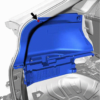
Remove the clip.
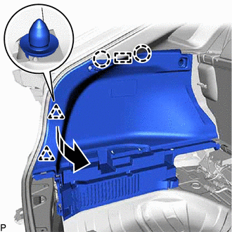

|
Separate in this Direction |
Disengage the 2 clips, 2 claws and guide to separate the deck trim side panel assembly as shown in the illustration.
- NOTICE:
-
Do not forcefully pull the deck trim side panel assembly as it may become damaged.
13.REMOVE REAR COMBINATION LIGHT ASSEMBLY WITH RETAINER
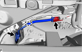
Disconnect the connector.
Disengage the clamp.
Disengage the grommet.
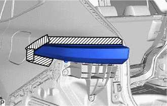

|
Protective Tape |
Apply protective tape around the rear combination light assembly with retainer as shown in the illustration.
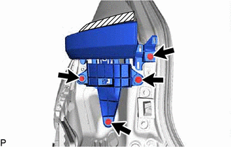
Remove the 4 screws.
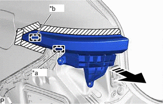
| *a | Pin |
| *b | Guide |
|
|
Remove in this Direction |
Pull the rear combination light assembly with retainer toward the rear of the vehicle as shown in the illustration to disengage the pin and guide and remove the rear combination light assembly with retainer.
- NOTICE:
-
To prevent the rear combination light assembly with retainer from falling when disengaging the pin and guide, make sure to hold the rear combination light assembly with retainer.
52563D
14.REMOVE REAR BUMPER UPPER RETAINER
81560
15.REMOVE REAR COMBINATION LIGHT ASSEMBLY