DOOR LOCK POWER DOOR LOCK CONTROL SYSTEM All Doors LOCK/UNLOCK Functions do not Operate Via Door Key Cylinder
DESCRIPTION
The main body ECU (multiplex network body ECU) receives driver door key cylinder lock or unlock switch signals from the front door lock with motor assembly. The main body ECU (multiplex network body ECU) activates the door lock motor on each door according to these signals.
WIRING DIAGRAM
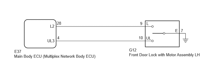
CAUTION / NOTICE / HINT
- NOTICE:
- ·
Before replacing the main body ECU (multiplex network body ECU), refer to Service Bulletin.
·The auxiliary battery supplies power to the main body ECU (multiplex network body ECU) via the door control battery. Therefore, before performing this troubleshooting procedure, make sure to perform an on-vehicle inspection to confirm that the main body ECU (multiplex network body ECU) power source circuit is normal.*
*: w/ Door Control Battery
PROCEDURE
Read the Data List according to the display on the GTS.
- Body Electrical > Main Body > Data List
-
Tester Display Measurement Item Range Normal Condition Diagnostic Note Door Lock Switch Status by a Mechanical Key (D/P Door) Driver door key-linked lock / unlock switch lock signal OFF or ON OFF: Driver door key cylinder not turned to lock position
ON: Driver door key cylinder turned to lock position- Door Unlock Switch Status by a Mechanical Key (D Door) Driver door key-linked lock / unlock switch unlock signal OFF or ON OFF: Driver door key cylinder not turned to unlock position
ON: Driver door key cylinder turned to unlock position-
- Body Electrical > Main Body > Data List
-
Tester Display Door Lock Switch Status by a Mechanical Key (D/P Door) Door Unlock Switch Status by a Mechanical Key (D Door) - 50003 449 11,14
- Result:
Proceed to OK NG
OK
NG
- Result:
Proceed to OK NG
OK
NG
Disconnect the E37 main body ECU (multiplex network body ECU) connector.
Measure the resistance according to the value(s) in the table below.
- Standard Resistance:
Tester Connection Condition Specified Condition Click Location & Routing(G12,E37)Location & Routingewd_type=routing;type=c,c;code=G12,E37
Click Connector(G12)Body>Front Door Wire RH / Front Door Wire LH>Front Door Lock with Motor Assembly LHewd_type=component;type=c;code=G12;pinno=9,10,7
Click Connector(E37)Instrument Panel>Instrument Panel Wire / Radio Wiring Sub-Assy / Telephone Computer Wire>Multiplex Network Body ECUewd_type=component;type=c;code=E37;pinno=28,4
G12-9 (L) - E37-28 (L2) Always Below 1 Ω G12-10 (UL) - E37-4 (UL3) Always Below 1 Ω G12-7 (E) - Body ground Always Below 1 Ω G12-9 (L) or E37-28 (L2) - Other terminals and body ground Always 10 kΩ or higher G12-10 (UL) or E37-4 (UL3) - Other terminals and body ground Always 10 kΩ or higher
- Result:
Proceed to OK NG
OK
NG