DOOR / HATCH POWER BACK DOOR SYSTEM Close & Lock Function does not Operate
DESCRIPTION
The door control switch signal is sent to the multiplex network door ECU. If the power back door system does not operate when the door control switch is operated, the door control switch assembly circuit may be malfunctioning.
WIRING DIAGRAM
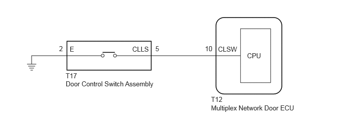
CAUTION / NOTICE / HINT
- NOTICE:
- ·
If the replacement, removal and installation of the multiplex network door ECU or disconnection of the connectors of the multiplex network door ECU has been performed, initialize the power back door system.
·Check the smart entry and start system (for Entry Function) first before troubleshooting the power back door system.
for HV Model: Click hereVehicle Interior>THEFT DETERRENT / KEYLESS ENTRY>SMART ENTRY AND START SYSTEM (for Entry Function, HV Model)>HOW TO PROCEED WITH TROUBLESHOOTING202111,999999,_58,_111832,_0509382,RM10000000204WE,
for Gasoline Model: Click hereVehicle Interior>THEFT DETERRENT / KEYLESS ENTRY>SMART ENTRY AND START SYSTEM (for Entry Function, Gasoline Model)>HOW TO PROCEED WITH TROUBLESHOOTING202111,999999,_58,_111832,_0509383,RM10000000204X8,
PROCEDURE
Read the Data List according to the display on the GTS.
- Body Electrical > Back Door > Data List
-
Tester Display Measurement Item Range Normal Condition Diagnostic Note Close and Lock Switch Door control switch signal ON or OFF ON: Door control switch pressed
OFF: Door control switch not pressed-
- Body Electrical > Back Door > Data List
-
Tester Display Close and Lock Switch - 50003 489 1050
- OK:
The display is as specified in the normal condition column.
- OK:
Proceed to OK NG
OK
NG
- OK:
Proceed to OK NG
OK
NG
Disconnect the T12 multiplex network door ECU connector.
Measure the resistance according to the value(s) in the table below.
- Standard Resistance:
Tester Connection Condition Specified Condition Click Location & Routing(T17,T12)Location & Routingewd_type=routing;type=c,c;code=T17,T12
Click Connector(T17)Body>No. 1 Back Door Wire>Door Control Switch Assembly (Power Back Door Reverse Lock Switch)ewd_type=component;type=c;code=T17;pinno=5,2
Click Connector(T12)Body>No. 1 Back Door Wire>Multiplex Network Door ECUewd_type=component;type=c;code=T12;pinno=10
T17-5 (CLLS) - T12-10 (CLSW) Always Below 1 Ω T17-2 (E) - Body ground Always Below 1 Ω T17-5 (CLLS) or T12-10 (CLSW) - Body ground Always 10 kΩ or higher
- OK:
Proceed to OK NG
OK
NG