LIGHTING (EXT) LIGHTING SYSTEM Back-up Light Circuit
DESCRIPTION
The hybrid vehicle control ECU controls the back-up lights via the BKUP LP relay.
WIRING DIAGRAM
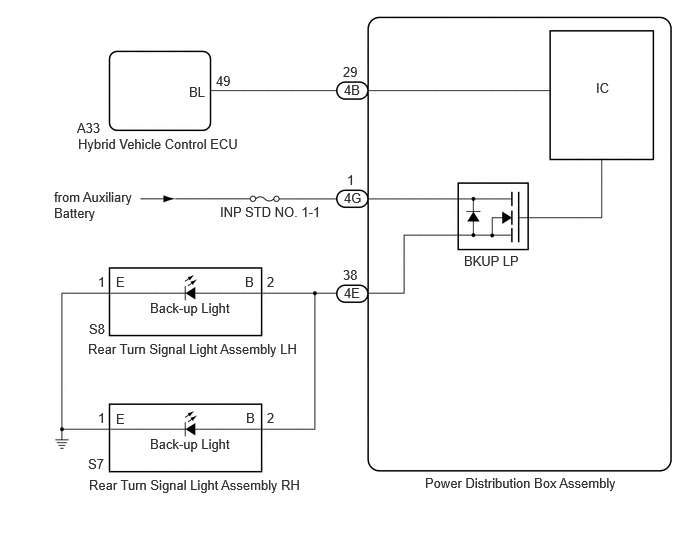
CAUTION / NOTICE / HINT
- NOTICE:
- ·
Inspect the fuses for circuits related to this system before performing the following procedure.
·Before replacing the hybrid vehicle control ECU, refer to Service Bulletin.
·When replacing the hybrid vehicle control ECU, update the ECU security key.
PROCEDURE
Turn the ignition switch to ON.
Move the shift lever to R.
Read the Data List according to the display on the GTS.
- Body Electrical > Power Distribution Box > Data List
-
Tester Display Measurement Item Normal Condition Reference Value Diagnostic Note Back-up Light Fuse Shut Off Status Back-up light fuse shut off status OFF or ON OFF: Fuse has no shut off history
ON: Fuse has shut off history-
- Body Electrical > Power Distribution Box > Data List
-
Tester Display Back-up Light Fuse Shut Off Status - 50003 475 1308
- OK:
The Data List value displays "OFF".
- Result:
Proceed to OK NG
OK
NG
Read the Data List according to the display on the GTS.
- Body Electrical > Power Distribution Box > Data List
-
Tester Display Measurement Item Normal Condition Reference Value Diagnostic Note Back-up Light Input Signal Back-up light input OFF or ON OFF: Shift lever in any position other than R
ON: Shift lever in R-
- Body Electrical > Power Distribution Box > Data List
-
Tester Display Back-up Light Input Signal - 50003 475 1305
- OK:
Display changes according to shift lever operation.
- Result:
Proceed to OK NG
OK
NG
Disconnect the 4G power distribution box assembly connector.
Measure the voltage according to the value(s) in the table below.
- Standard Voltage:
Tester Connection Condition Specified Condition 4G-1 - Body ground Ignition switch off 11 to 14 V
- Result:
Proceed to OK NG
OK
NG
Disconnect the S8 rear turn signal light assembly LH connector.
Disconnect the S7 rear turn signal light assembly RH connector.
Disconnect the 4E power distribution box assembly connector.
Measure the resistance according to the value(s) in the table below.
- Standard Resistance:
Tester Connection Condition Specified Condition Click Location & Routing(S8,S7)Location & Routingewd_type=routing;type=c,c;code=S8,S7
Click Connector(S8)Body>No. 2 Luggage Room Wire / No. 3 Luggage Room Wire>Rear Turn Signal Light Assembly LHewd_type=component;type=c;code=S8;pinno=2
Click Connector(S7)Body>No. 2 Luggage Room Wire / No. 3 Luggage Room Wire>Rear Turn Signal Light Assembly RHewd_type=component;type=c;code=S7;pinno=2
S8-2 (B) - 4E-38 Always Below 1 Ω S7-2 (B) - 4E-38 Always Below 1 Ω
- Result:
Proceed to OK NG
OK
NG
Measure the resistance according to the value(s) in the table below.
- Standard Resistance:
Tester Connection Condition Specified Condition Click Location & Routing(S8,S7)Location & Routingewd_type=routing;type=c,c;code=S8,S7
Click Connector(S8)Body>No. 2 Luggage Room Wire / No. 3 Luggage Room Wire>Rear Turn Signal Light Assembly LHewd_type=component;type=c;code=S8;pinno=1
Click Connector(S7)Body>No. 2 Luggage Room Wire / No. 3 Luggage Room Wire>Rear Turn Signal Light Assembly RHewd_type=component;type=c;code=S7;pinno=1
S8-1 (E) - Body ground Always Below 1 Ω S7-1 (E) - Body ground Always Below 1 Ω
- Result:
Proceed to OK NG
OK
NG
Disconnect the A33 hybrid vehicle control ECU connector.
Disconnect the 4B power distribution box assembly connector.
Measure the resistance according to the value(s) in the table below.
- Standard Resistance:
Tester Connection Condition Specified Condition Click Location & Routing(A33)Location & Routingewd_type=routing;type=c;code=A33
Click Connector(A33)Instrument Panel>Engine Room Main Wire>Hybrid Vehicle Control ECUewd_type=component;type=c;code=A33;pinno=49
A33-49 (BL) - 4B-29 Always Below 1 Ω A33-49 (BL) or 4B-29 - Body ground Always 10 kΩ or higher
- Result:
Proceed to OK NG
OK
NG
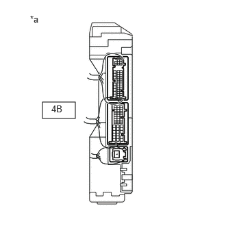
| *a | Component with harness connected
(Power Distribution Box Assembly) |
Connect the A33 hybrid vehicle control ECU connector.
Connect the 4B power distribution box assembly connector.
Measure the voltage according to the value(s) in the table below.
- Standard Voltage:
Tester Connection Condition Specified Condition 4B-29 - Body ground Ignition switch ON, reverse (R) not selected Below 1 V 4B-29 - Body ground Ignition switch ON, reverse (R) selected 11 to 14 V
- Result:
Proceed to OK NG
OK
NG
Disconnect the S8 rear turn signal light assembly LH connector.
Turn the ignition switch to ON.
Move the shift lever to R.
Read the Data List according to the display on the GTS.
- Body Electrical > Power Distribution Box > Data List
-
Tester Display Measurement Item Normal Condition Reference Value Diagnostic Note Back-up Light Fuse Shut Off Status Back-up light fuse shut off status OFF or ON OFF: Fuse has no shut off history
ON: Fuse has shut off history-
- Body Electrical > Power Distribution Box > Data List
-
Tester Display Back-up Light Fuse Shut Off Status - 50003 475 1308
- OK:
The Data List value displays "OFF".
- Result:
Proceed to OK NG
OK
NG
Disconnect the S7 rear turn signal light assembly RH connector.
Turn the ignition switch to ON.
Move the shift lever to R.
Read the Data List according to the display on the GTS.
- Body Electrical > Power Distribution Box > Data List
-
Tester Display Measurement Item Normal Condition Reference Value Diagnostic Note Back-up Light Fuse Shut Off Status Back-up light fuse shut off status OFF or ON OFF: Fuse has no shut off history
ON: Fuse has shut off history-
- Body Electrical > Power Distribution Box > Data List
-
Tester Display Back-up Light Fuse Shut Off Status - 50003 475 1308
- OK:
The Data List value displays "OFF".
- Result:
Proceed to OK NG
OK
NG
Disconnect the 4E power distribution box assembly connector.
Measure the resistance according to the value(s) in the table below.
- Standard Resistance:
Tester Connection Condition Specified Condition Click Location & Routing(S8,S7)Location & Routingewd_type=routing;type=c,c;code=S8,S7
Click Connector(S8)Body>No. 2 Luggage Room Wire / No. 3 Luggage Room Wire>Rear Turn Signal Light Assembly LHewd_type=component;type=c;code=S8;pinno=2
Click Connector(S7)Body>No. 2 Luggage Room Wire / No. 3 Luggage Room Wire>Rear Turn Signal Light Assembly RHewd_type=component;type=c;code=S7;pinno=2
S8-2 (B), S7-2 (B) or 4E-38 - Body ground Always 10 kΩ or higher
- Result:
Proceed to OK NG
OK
NG