LIGHTING (INT) LIGHTING SYSTEM Door Unlock Detection Switch Circuit
DESCRIPTION
The main body ECU (multiplex network body ECU) detects the condition of each door unlock detection switch.
WIRING DIAGRAM
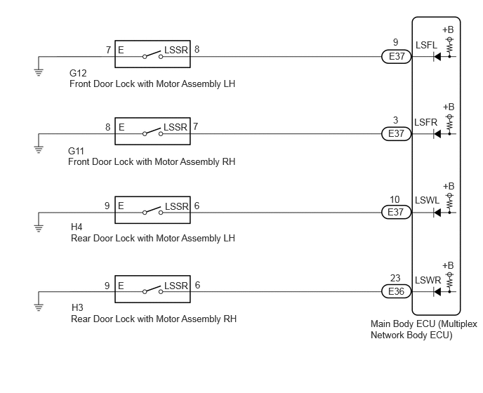
CAUTION / NOTICE / HINT
- NOTICE:
-
Before replacing the main body ECU (multiplex network body ECU), refer to Service Bulletin.
PROCEDURE
Read the Data List according to the display on the GTS.
- Body Electrical > Main Body > Data List
-
Tester Display Measurement Item Range Normal Condition Diagnostic Note FR Door Lock Position Switch Status Front door RH unlock detection switch signal Lock or Unlock Lock: Front door RH locked
Unlock: Front door RH unlocked- FL Door Lock Position Switch Status Front door LH unlock detection switch signal Lock or Unlock Lock: Front door LH locked
Unlock: Front door LH unlocked- RR Door Lock Position Switch Status Rear door RH unlock detection switch signal Lock or Unlock Lock: Rear door RH locked
Unlock: Rear door RH unlocked- RL Door Lock Position Switch Status Rear door LH unlock detection switch signal Lock or Unlock Lock: Rear door LH locked
Unlock: Rear door LH unlocked-
- Body Electrical > Main Body > Data List
-
Tester Display FR Door Lock Position Switch Status FL Door Lock Position Switch Status RR Door Lock Position Switch Status RL Door Lock Position Switch Status - 50003 449 20,21,22,23
- OK:
Normal conditions listed above are displayed.
- Result:
Result Proceed to OK A NG ("FL Door Lock Position Switch Status" is not normal) B NG ("FR Door Lock Position Switch Status" is not normal) C NG ("RL Door Lock Position Switch Status" is not normal) D NG ("RR Door Lock Position Switch Status" is not normal) E
A
B
C
D
E
- Result:
Proceed to OK NG
OK
NG
Disconnect the E37 main body ECU (multiplex network body ECU) connector.
Measure the resistance according to the value(s) in the table below.
- Standard Resistance:
Tester Connection Condition Specified Condition Click Location & Routing(G12,E37)Location & Routingewd_type=routing;type=c,c;code=G12,E37
Click Connector(G12)Body>Front Door Wire RH / Front Door Wire LH>Front Door Lock with Motor Assembly LHewd_type=component;type=c;code=G12;pinno=8,7
Click Connector(E37)Instrument Panel>Instrument Panel Wire / Radio Wiring Sub-Assy / Telephone Computer Wire>Multiplex Network Body ECUewd_type=component;type=c;code=E37;pinno=9
G12-8 (LSSR) - E37-9 (LSFL) Always Below 1 Ω G12-8 (LSSR) or E37-9 (LSFL) - Body ground Always 10 kΩ or higher G12-7 (E) - Body ground Always Below 1 Ω
- Result:
Proceed to OK NG
OK
NG
- Result:
Proceed to OK NG
OK
NG
Disconnect the E37 main body ECU (multiplex network body ECU) connector.
Measure the resistance according to the value(s) in the table below.
- Standard Resistance:
Tester Connection Condition Specified Condition Click Location & Routing(G11,E37)Location & Routingewd_type=routing;type=c,c;code=G11,E37
Click Connector(G11)Body>Front Door Wire RH / Front Door Wire LH>Front Door Lock with Motor Assembly RHewd_type=component;type=c;code=G11;pinno=7,8
Click Connector(E37)Instrument Panel>Instrument Panel Wire / Radio Wiring Sub-Assy / Telephone Computer Wire>Multiplex Network Body ECUewd_type=component;type=c;code=E37;pinno=3
G11-7 (LSSR) - E37-3 (LSFR) Always Below 1 Ω G11-7 (LSSR) or E37-3 (LSFR) - Body ground Always 10 kΩ or higher G11-8 (E) - Body ground Always Below 1 Ω
- Result:
Proceed to OK NG
OK
NG
- Result:
Proceed to OK NG
OK
NG
Disconnect the E37 main body ECU (multiplex network body ECU) connector.
Measure the resistance according to the value(s) in the table below.
- Standard Resistance:
Tester Connection Condition Specified Condition Click Location & Routing(H4,E37)Location & Routingewd_type=routing;type=c,c;code=H4,E37
Click Connector(H4)Body>No. 1 Rear Door Wire / No. 2 Rear Door Wire>Rear Door Lock with Motor Assembly LHewd_type=component;type=c;code=H4;pinno=6,9
Click Connector(E37)Instrument Panel>Instrument Panel Wire / Radio Wiring Sub-Assy / Telephone Computer Wire>Multiplex Network Body ECUewd_type=component;type=c;code=E37;pinno=10
H4-6 (LSSR) - E37-10 (LSWL) Always Below 1 Ω H4-6 (LSSR) or E37-10 (LSWL) - Body ground Always 10 kΩ or higher H4-9 (E) - Body ground Always Below 1 Ω
- Result:
Proceed to OK NG
OK
NG
- Result:
Proceed to OK NG
OK
NG
Disconnect the E36 main body ECU (multiplex network body ECU) connector.
Measure the resistance according to the value(s) in the table below.
- Standard Resistance:
Tester Connection Condition Specified Condition Click Location & Routing(H3,E36)Location & Routingewd_type=routing;type=c,c;code=H3,E36
Click Connector(H3)Body>No. 1 Rear Door Wire / No. 2 Rear Door Wire>Rear Door Lock with Motor Assembly RHewd_type=component;type=c;code=H3;pinno=6,9
Click Connector(E36)Instrument Panel>Instrument Panel Wire / Radio Wiring Sub-Assy / Telephone Computer Wire>Multiplex Network Body ECUewd_type=component;type=c;code=E36;pinno=23
H3-6 (LSSR) - E36-23 (LSWR) Always Below 1 Ω H3-6 (LSSR) or E36-23 (LSWR) - Body ground Always 10 kΩ or higher H3-9 (E) - Body ground Always Below 1 Ω
- Result:
Proceed to OK NG
OK
NG