HEATING / AIR CONDITIONING AIR CONDITIONING SYSTEM(for Gasoline Model) Cooling is Poor
DESCRIPTION
If the cooling effect of the air conditioning system is weak, the following factors may be the cause.
| Symptom | Factor |
|---|---|
·
Cooling effectiveness is poor ·
Cooling response is slow |
·
ECO mode control of air conditioning system is enabled ·
Compressor assembly with pulley malfunction ·
Refrigerant volume (high) ·
Refrigerant volume (low) ·
Clogged cooler condenser assembly fins ·
Cooling fan system malfunction ·
Mechanical locking of damper and damper link ·
Automatic light control sensor malfunction ·
High inlet air temperature ·
Harness or connector |
WIRING DIAGRAM
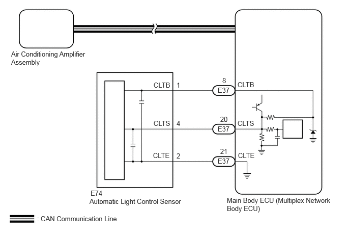
PROCEDURE
Confirm that ECO HEAT/COOL switch (air conditioning control assembly) is set to off.
Confirm that ECO drive mode is set to off.
- HINT:
-
When the ECO drive mode is set to ON, the air conditioning amplifier assembly performs minimal air conditioning control in order to promote the improvement of fuel economy. Ensure that the customer understands that the airflow volume will be decreased compared to normal operation.
Control Control Summary Air Volume Control Sets the blower level to less.
- Result:
Proceed to NEXT
NEXT
Prepare the vehicle according to the table below.
| Item | Condition |
|---|---|
| A/C Switch | On |
| Ambient Temperature*1 | 0 to 49°C (32 to 120°F) |
| Air Conditioning Air Inlet Temperature*2 | 25 to 35°C (77 to 95°F) |
| Set Temperature | MAX COLD |
| Recirculation/fresh Control Switch | Recirculation |
| Air Vent Damper Position | FACE |
| Blower Speed | HI |
- HINT:
-
*1: This inspection can be judged correctly only if the ambient temperature is within a range of 0 to 49°C (32 to 120°F). Therefore, postpone the test if the temperature is low.
-
*2: This inspection can be judged correctly only if the air inlet temperature is within a range of 25 to 35°C (77 to 95°F). Therefore, postpone the test if the temperature is out of range.
Using the GTS, check the amount of refrigerant.
- Body Electrical > Air Conditioner > Utility
-
Tester Display Refrigerant Gas Volume Check - 50005 450 4578
- NOTICE:
-
If the conditions for the inspection are not met, "Refrigerant incorrect" will be displayed on the GTS. Confirm the conditions of the inspection and perform the check again.
- HINT:
- ·
If the amount of refrigerant is insufficient, "Refrigerant shortage" is displayed on the GTS and the indicator light on the A/C switch turns off.
·When performing this inspection, a DTC will not be output even if "Refrigerant shortage" is displayed on the GTS.
- Result:
Result Amount of Refrigerant Refrigerant shortage Insufficient or leakage Refrigerant correct Correct Refrigerant incorrect Incorrect
- OK:
"Refrigerant correct" is displayed on the GTS.
- Result:
Proceed to OK NG
OK
NG
Perform the Active Test according to the display on the GTS.
- Body Electrical > Air Conditioner > Active Test
-
Tester Display Measurement Item Control Range Diagnostic Note Front Left Air Mix Damper Control Servo Motor This test activates the Front Left Air Mix Damper Control Servo Motor.
(No. 1 air conditioning radiator damper servo sub-assembly (front left side air mix))128: Min
384: MaxOperate with ignition switch ON. Front Right Air Mix Damper Control Servo Motor This test activates the Front Right Air Mix Damper Control Servo Motor.
(No. 1 air conditioning radiator damper servo sub-assembly (front right side air mix))128: Min
384: MaxOperate with ignition switch ON.
- Body Electrical > Air Conditioner > Active Test
-
Active Test Display Front Left Air Mix Damper Control Servo Motor -
Data List Display Front Left Air Mix Damper Control Servo Motor Actual Pulse - 50004 450 26 201
- Body Electrical > Air Conditioner > Active Test
-
Active Test Display Front Right Air Mix Damper Control Servo Motor -
Data List Display Front Right Air Mix Damper Control Servo Motor Actual Pulse - 50004 450 28 205
- OK:
Damper servo motor is operated.
- Result:
Proceed to OK NG
OK
NG
Disconnect the E74 automatic light control sensor connector.
Disconnect the E37 main body ECU (multiplex network body ECU) connector.
Measure the resistance according to the value(s) in the table below.
- Standard Resistance:
Tester Connection Condition Specified Condition Click Location & Routing(E74,E37)Location & Routingewd_type=routing;type=c,c;code=E74,E37
Click Connector(E74)Instrument Panel>Instrument Panel Wire / Telephone Computer Wire>Automatic Light Control Sensorewd_type=component;type=c;code=E74;pinno=1,2,4
Click Connector(E37)Instrument Panel>Instrument Panel Wire / Telephone Computer Wire>Multiplex Network Body ECUewd_type=component;type=c;code=E37;pinno=8,21,20
E74-1 (CLTB) - E37-8 (CLTB) Always Below 1 Ω E74-2 (CLTE) - E37-21 (CLTE) Always Below 1 Ω E74-4 (CLTS) - E37-20 (CLTS) Always Below 1 Ω E74-1 (CLTB) or E37-8 (CLTB) - Other terminals and body ground Always 10 kΩ or higher E74-2 (CLTE) or E37-21 (CLTE) - Other terminals and body ground Always 10 kΩ or higher E74-4 (CLTS) or E37-20 (CLTS) - Other terminals and body ground Always 10 kΩ or higher
- Result:
Proceed to OK NG
OK
NG
- Result:
Proceed to OK NG
OK
NG