LIGHTING (EXT) AUTOMATIC LIGHT CONTROL SENSOR ON-VEHICLE INSPECTION
PROCEDURE

 89120A
1.INSPECT AUTOMATIC LIGHT CONTROL SENSOR
89120A
1.INSPECT AUTOMATIC LIGHT CONTROL SENSOR
Disconnect the E74 automatic light control sensor connector.
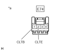
| *a | Front view of wire harness connector
(to Automatic Light Control Sensor) |
Measure the voltage and resistance according to the value(s) in the table below.
- Standard Voltage:
Tester Connection Condition Specified Condition Click Location & Routing(E74)Location & Routingewd_type=routing;type=c;code=E74
Click Connector(E74)Instrument Panel>Instrument Panel Wire / Radio Wiring Sub-Assy / Telephone Computer Wire>Automatic Light Control Sensorewd_type=component;type=c;code=E74;pinno=1,2
E74-1 (CLTB) - E74-2 (CLTE) Ignition switch on (IG) 11 to 14 V
- Standard Resistance:
Tester Connection Condition Specified Condition Click Location & Routing(E74)Location & Routingewd_type=routing;type=c;code=E74
Click Connector(E74)Instrument Panel>Instrument Panel Wire / Radio Wiring Sub-Assy / Telephone Computer Wire>Automatic Light Control Sensorewd_type=component;type=c;code=E74;pinno=2
E74-2 (CLTE) - Body ground Always Below 1 Ω
If the result is not as specified, there may be a malfunction on the wire harness side.
Connect the E74 automatic light control sensor connector.
Connect an oscilloscope to terminals E74-2 (CLTE) and E74-4 (CLTS) of the automatic light control sensor connector and check the waveform.

| *a | Component with harness connected
(Automatic Light Control Sensor) |
*b | Waveform |
- OK:
Tester Connection Condition Tool Setting Specified Condition Click Location & Routing(E74)Location & Routingewd_type=routing;type=c;code=E74
Click Connector(E74)Instrument Panel>Instrument Panel Wire / Radio Wiring Sub-Assy / Telephone Computer Wire>Automatic Light Control Sensorewd_type=component;type=c;code=E74;pinno=2,4
E74-2 (CLTE) - E74-4 (CLTS) Ignition switch on (IG) 2 V/DIV., 10 ms./DIV. Pulse generation
(See waveform)
- HINT:
-
The communication waveform changes according to the surrounding brightness.
If the result is not as specified, the automatic light control sensor may be malfunctioning.