HEATING / AIR CONDITIONING REFRIGERANT ON-VEHICLE INSPECTION
CAUTION / NOTICE / HINT
- HINT:
- ·
Steps 2 to 9 specify the procedure to determine the cause of a refrigerant leak.
·Step 10 specifies the procedure to check if there is a clog in the expansion valve.
PROCEDURE

 1.INSPECT REFRIGERANT PRESSURE WITH MANIFOLD GAUGE SET
- HINT:
-
The following examples show the readings of a manifold gauge set and the corresponding air conditioning system problems.
Read the manifold gauge pressure when the following conditions are met:
The doors are fully open.
The engine is idling (for Gasoline Model) or the ignition switch is ON (READY) (for HV Model).
The A/C switch is on.
The temperature is set to max cold.
The blower speed is set to high.
The temperature at the air inlet with recirculate selected is 30 to 35°C (86 to 95°F).
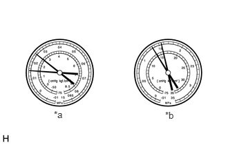
| *a | LO |
| *b | HI |
Normal functioning air conditioning system
| Pressure Side | Specified Condition |
|---|---|
| Low | 150 to 250 kPa
1.5 to 2.5 kgf/cm2 22 to 36 psi |
| High | 1370 to 1570 kPa
14.0 to 16.0 kgf/cm2 199 to 228 psi |
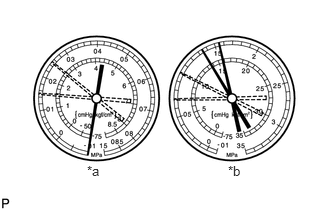
| *a | LO |
| *b | HI |
Abnormally functioning air conditioning system
During operation, pressure on low pressure side cycles between normal and vacuum
| Symptom | Air conditioning system periodically cools and then fails to cool |
| Probable Cause | Moisture in air conditioning system freezes at expansion valve orifice, causing refrigerant to temporarily stop circulating |
| After system stops and warms up again, ice melts and normal operation is temporarily restored | |
| Diagnosis | Cooler dryer (integrated into condenser tank) saturated with moisture |
| Moisture in air conditioning system is freezing at expansion valve orifice and blocking circulation of refrigerant | |
| Corrective Actions | Replace cooler dryer |
| Remove moisture by repeatedly evacuating air from air conditioning system | |
| Recharge air conditioning system with proper amount of new or purified refrigerant |
- HINT:
-
For the example above, moisture is present in the air conditioning system.
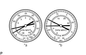
| *a | LO |
| *b | HI |
Pressure is low on both low and high pressure sides
| Symptom | Air conditioning system does not cool effectively |
| Insufficient cooling performance | |
| Probable Cause | Refrigerant leaks from air conditioning system |
| Diagnosis | Insufficient refrigerant |
| Refrigerant leaking | |
| Corrective Actions | Check for refrigerant leaks and repair if necessary |
| Recharge air conditioning system with proper amount of new or purified refrigerant | |
| If gauges indicate pressure of close to 0, then it is necessary to evacuate air conditioning system after repairing leaks |
- HINT:
-
For the example above, there is insufficient refrigerant.
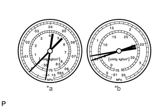
| *a | LO |
| *b | HI |
Pressure is low on both low and high pressure sides
| Symptom | Air conditioning system does not cool effectively |
| Frost exists on pipe from condenser to evaporator unit | |
| Probable Cause | Refrigerant flow is obstructed by dirt inside pipes of condenser core |
| Diagnosis | Condenser is clogged |
| Corrective Actions | Replace condenser |
- HINT:
-
For the example above, there is poor circulation of refrigerant.
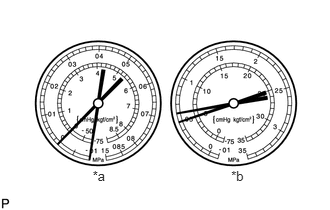
| *a | LO |
| *b | HI |
Vacuum is indicated on low pressure side and very low pressure is indicated on high pressure side
| Symptom | Air conditioning system does not cool effectively (System may cool occasionally) |
| Frost or condensation is seen on piping on both sides of receiver/dryer or expansion valve | |
| Probable Cause | Refrigerant flow is obstructed by moisture or dirt in air conditioning system |
| Expansion valve is stuck closed | |
| Diagnosis | Refrigerant does not circulate |
| Corrective Actions | Replace expansion valve |
| Replace condenser | |
| Evacuate air conditioning system and recharge with proper amount of new or purified refrigerant |
- HINT:
-
For the example above, the refrigerant does not circulate.
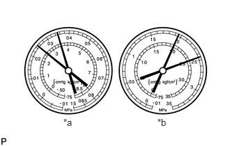
| *a | LO |
| *b | HI |
Pressure is too high on both low and high pressure sides
| Symptom | Air conditioning system does not cool effectively |
| Probable Cause | Unable to provide sufficient performance due to excessive amount of refrigerant |
| Cooling effectiveness of condenser is insufficient | |
| Diagnosis | Excessive amount of refrigerant in air conditioning system because excessive refrigerant was added during recharging |
| Cooling effectiveness of condenser is insufficient because condenser fins are clogged or cooling fan is faulty | |
| Corrective Actions | Clean condenser |
| Check operation of condenser cooling fan | |
| If condenser is clean and fan operation is normal, check amount of refrigerant and recharge air conditioning system with proper amount of new or purified refrigerant |
- HINT:
-
For the example above, the air conditioning system is overcharged or cooling effectiveness of condenser is insufficient.
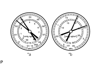
| *a | LO |
| *b | HI |
Pressure is too high on both low and high pressure sides
| Symptom | Air conditioning system does not cool |
| The low pressure piping is too hot to touch | |
| Probable Cause | Air in air conditioning system |
| Diagnosis | Air present in air conditioning system |
| Insufficient vacuum purging when evacuating air conditioning system | |
| Corrective Actions | Replace cooler dryer |
| Check compressor oil to see if it is dirty or insufficient | |
| Evacuate air conditioning system and recharge it with new or purified refrigerant |
- NOTICE:
-
These gauge indications occur when the air conditioning system has been left open and then recharged without evacuating the system.
- HINT:
-
For the example above, air is present in the air conditioning system.
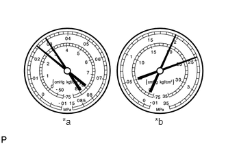
| *a | LO |
| *b | HI |
Pressure is too high on both low and high pressure sides
| Symptom | Air conditioning system does not cool effectively |
| Frost or large amount of condensation on piping on low pressure side | |
| Probable Cause | Expansion valve may be stuck open or metering refrigerant incorrectly |
| Diagnosis | Excessive refrigerant in low pressure piping |
| Expansion valve open too wide | |
| Corrective Actions | Replace expansion valve |
- HINT:
-
For the example above, there is an expansion valve malfunction.
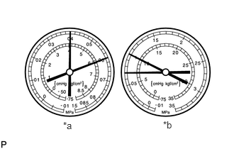
| *a | LO |
| *b | HI |
Pressure is too high on both low and high pressure sides or pressure is too low on high pressure side
| Symptom | Air conditioning system does not cool effectively |
| Probable Cause | Internal leak in compressor |
| Diagnosis | Low compression |
| Leak from damaged valve or other compressor component | |
| Corrective Actions | Replace compressor |
- HINT:
-
For the example above, there is insufficient compressor compression.
Gauge readings (Reference)
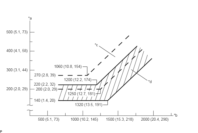
| *a | Pressure on Low Pressure Side kPa (kgf/cm2, psi) | *b | Pressure on High Pressure Side kPa (kgf/cm2, psi) |
| *c | Blower High Zone | *d | Blower Low Zone |
2. REFRIGERANT LINE
- HINT:
-
The following inspection specifies how to determine the cause of a refrigerant leak after determining the location of the leak using a gas leak detector. Use this procedure to determine where to clean and what to be replaced. Illustrations, specifications and part names are for reference only and may differ from the actual vehicle.
Use a gas leak detector to inspect for refrigerant gas leaks.
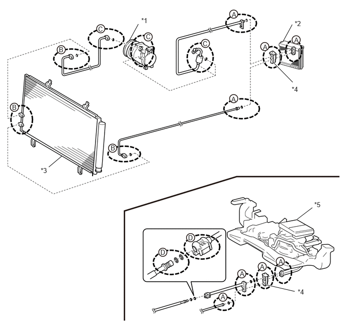
| *1 | Compressor | *2 | Evaporator |
| *3 | Condenser | *4 | Expansion Valve |
| *5 | Rear Air Conditioning Unit | - | - |
When leaking is occurring around the parts (A) in the illustration:
When leaking is occurring around the parts (B) in the illustration:
When leaking is occurring around the parts (C) in the illustration:
When leaking is occurring around the parts (D) in the illustration:
3.INSPECT FOR REFRIGERANT LEAK (EXPANSION VALVE)
- NOTICE:
- ·
Do not reuse an O-ring that has been removed.
·As there may be a malfunction in multiple components, make sure to perform the entire procedure.
·If no malfunction is found in any related parts, a temporary leak may have occurred due to foreign matter on an O-ring, deformation, etc.

| *1 | Expansion Valve |
| *a | Pipe |
Remove the pipe:
- NOTICE:
- ·
Wipe off the joint area with clean cloth before disassembly.
·Remove the pipe straight and slowly to prevent damage to the sealing surface, and to stop foreign matter from falling.
Remove the pipe from the expansion valve.
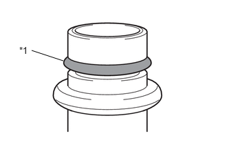
| *1 | O-ring |
Check the surface of the O-ring:
- NOTICE:
- ·
Check the surface of the O-ring in a sufficiently bright area.
·Degrease the surface if it is difficult to see due to oil, etc. Make sure not to lose any foreign matter that may indicate the source of a leak.
Check the entire surface of the O-ring and make sure that it is free from defects such as damage (cuts, crushing, indents, etc.), foreign matter or twisting. Remove all foreign matter or replace the part if there is any damage.

| *a | Sealing Surface |
Check the sealing surface of the pipe:
- NOTICE:
-
When removing the O-ring, be careful not to damage the O-ring or sealing surface.
Remove the O-ring.
Check the sealing surface of the pipe. Remove all foreign matter or replace the part if there is any damage or corrosion.
| *a | Sealing Surface |
Check the sealing surface of the expansion valve (pipe side):
- NOTICE:
-
Degrease the surface if it is difficult to see due to oil, etc. Make sure not to lose any foreign matter that may indicate the source of a leak.
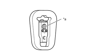
Check the entire sealing surface of the expansion valve (pipe side). Remove all foreign matter or replace the part if there is any damage or corrosion.
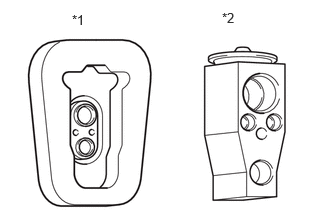
| *1 | Evaporator |
| *2 | Expansion Valve |
Remove the expansion valve:
- NOTICE:
- ·
Wipe off the joint area with clean cloth before disassembly.
·Remove the pipe straight and slowly to prevent damage to the sealing surface, and to stop foreign matter from falling.
·If the pipe is difficult to remove, wiggle it up and down and side to side while slowly removing it.
Remove the expansion valve from the evaporator.
- HINT:
-
If necessary, remove the air conditioning unit assembly.
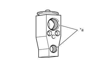
| *a | Sealing Surface |
Check the sealing surface of the expansion valve (evaporator side):
- NOTICE:
-
Degrease the surface if it is difficult to see due to oil, etc. Make sure not to lose any foreign matter that may indicate the source of a leak.
Check the entire sealing surface of the expansion valve (evaporator side). Remove all foreign matter or replace the part if there is any damage or corrosion.
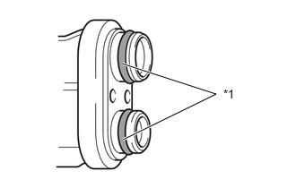
| *1 | O-ring |
Check the surface of the evaporator O-ring:
- NOTICE:
- ·
Check the surface of the O-ring in a sufficiently bright area.
·Degrease the surface if it is difficult to see due to oil, etc. Make sure not to lose any foreign matter that may indicate the source of a leak.
Check the entire surface of the O-ring and make sure that it is free from defects such as damage (cuts, crushing, indents, etc.), foreign matter or twisting. Remove all foreign matter or replace the part if there is any damage.
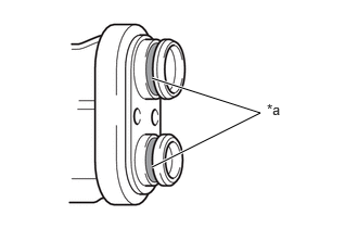
| *a | Sealing Surface |
Check the sealing surface of the evaporator:
- NOTICE:
-
When removing the O-ring, be careful not to damage the O-ring or sealing surface.
Remove the O-ring.
Check the entire sealing surface of the evaporator. Remove all foreign matter or replace the part if there is any damage or corrosion.
4.INSPECT FOR REFRIGERANT LEAK (CONDENSER)
- NOTICE:
- ·
Do not reuse an O-ring that has been removed.
·As there may be a malfunction in multiple components, make sure to perform the entire procedure.
·If no malfunction is found in any related parts, a temporary leak may have occurred due to foreign matter on an O-ring, deformation, etc.
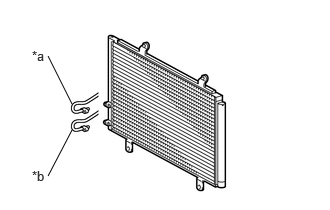
| *a | Discharge Side |
| *b | Liquid Side |
Remove the pipe:
- NOTICE:
- ·
Wipe off the joint area with clean cloth before disassembly.
·Remove the pipe straight and slowly to prevent damage to the sealing surface, and to stop foreign matter from falling.
Remove the pipe from the condenser.
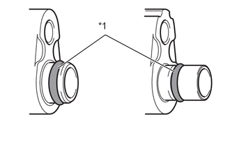
| *1 | O-ring |
Check the surface of the O-ring:
- NOTICE:
- ·
Check the surface of the O-ring in a sufficiently bright area.
·Degrease the surface if it is difficult to see due to oil, etc. Make sure not to lose any foreign matter that may indicate the source of a leak.
Check the entire surface of the O-ring and make sure that it is free from defects such as damage (cuts, crushing, indents, etc.), foreign matter or twisting. Remove all foreign matter or replace the part if there is any damage.
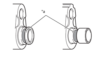
| *a | Sealing Surface |
Check the sealing surface of the pipe:
- NOTICE:
-
When removing the O-ring, be careful not to damage the O-ring or sealing surface.
Remove the O-ring.
Check the sealing surface of the pipe. Remove all foreign matter or replace the part if there is any damage or corrosion.
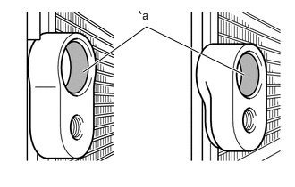
| *a | Sealing Surface |
Check the sealing surface of the condenser:
- NOTICE:
-
Degrease the surface if it is difficult to see due to oil, etc. Make sure not to lose any foreign matter that may indicate the source of a leak.
Check the entire sealing surface of the condenser. Remove all foreign matter or replace the part if there is any damage or corrosion.
5.INSPECT FOR REFRIGERANT LEAK (COMPRESSOR)
- NOTICE:
- ·
Do not reuse an O-ring that has been removed.
·As there may be a malfunction in multiple components, make sure to perform the entire procedure.
·If no malfunction is found in any related parts, a temporary leak may have occurred due to foreign matter on an O-ring, deformation, etc.
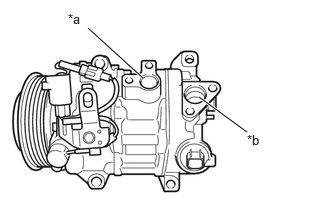
| *a | Discharge Side |
| *b | Suction Side |
Remove the pipe:
- NOTICE:
- ·
Wipe off the joint area with clean cloth before disassembly.
·Remove the pipe straight and slowly to prevent damage to the sealing surface, and to stop foreign matter from falling.
Remove the pipe from the compressor.
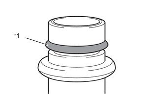
| *1 | O-ring |
Check the surface of the O-ring:
- NOTICE:
- ·
Check the surface of the O-ring in a sufficiently bright area.
·Degrease the surface if it is difficult to see due to oil, etc. Make sure not to lose any foreign matter that may indicate the source of a leak.
Check the entire surface of the O-ring and make sure that it is free from defects such as damage (cuts, crushing, indents, etc.), foreign matter or twisting. Remove all foreign matter or replace the part if there is any damage.
| *a | Sealing Surface |
Check the sealing surface of the pipe:
- NOTICE:
-
When removing the O-ring, be careful not to damage the O-ring or sealing surface.
Remove the O-ring.
Check the sealing surface of the pipe. Remove all foreign matter or replace the part if there is any damage or corrosion.
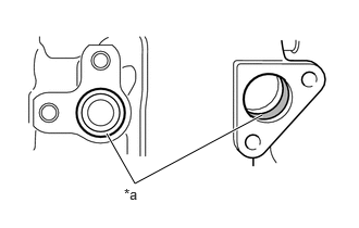
| *a | Sealing Surface |
Check the sealing surface of the compressor:
- NOTICE:
-
Degrease the surface if it is difficult to see due to oil, etc. Make sure not to lose any foreign matter that may indicate the source of a leak.
Check the entire sealing surface of the compressor. Remove all foreign matter or replace the part if there is any damage or corrosion.
6.INSPECT FOR REFRIGERANT LEAK (OTHER PARTS)
- NOTICE:
- ·
Do not reuse an O-ring that has been removed.
·As there may be a malfunction in multiple components, make sure to perform the entire procedure.
·If no malfunction is found in any related parts, a temporary leak may have occurred due to foreign matter on an O-ring, deformation, etc.
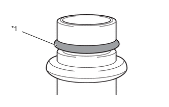
| *1 | O-ring |
Check the surface of the pipe O-ring or component O-ring:
- NOTICE:
- ·
Check the surface of the O-ring in a sufficiently bright area.
·Degrease the surface if it is difficult to see due to oil, etc. Make sure not to lose any foreign matter that may indicate the source of a leak.
Check the entire surface of the O-ring and make sure that it is free from defects such as damage (cuts, crushing, indents, etc.), foreign matter or twisting. Remove all foreign matter or replace the part if there is any damage.
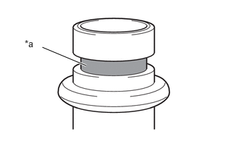
| *a | Sealing Surface |
Check the sealing surface of the pipe:
- NOTICE:
-
When removing the O-ring, be careful not to damage the O-ring or sealing surface.
Remove the O-ring.
Check the sealing surface of the pipe. Remove all foreign matter or replace the part if there is any damage or corrosion.
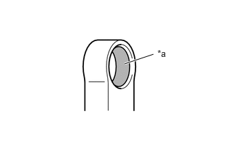
| *a | Sealing Surface |
Inspect the sealing surface of the parts:
- NOTICE:
-
Degrease the surface if it is difficult to see due to oil, etc. Make sure not to lose any foreign matter that may indicate the source of a leak.
Check the entire sealing surface of the parts. Remove all foreign matter or replace the part if there is any damage or corrosion.
7.INSPECT O-RING
- NOTICE:
-
Do not reuse an O-ring that has been removed.
Check the O-ring for abnormalities.
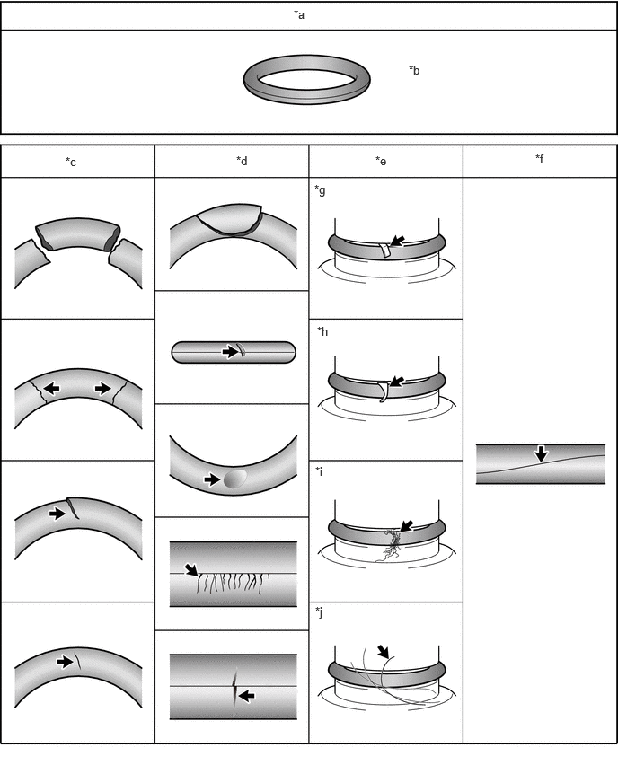
| *a | OK Condition | *b | Free of cuts, crushing, indents, foreign matter and twisting. |
| *c | Cuts | *d | Crushing/Indents |
| *e | Foreign Matter | *f | Twisting |
| *g | Metal Fragments | *h | Resin Fragments |
| *i | Lint | *j | Hair |
8.INSPECT SEALING SURFACE (O-RING INSTALLATION AREA)
- NOTICE:
-
Do not reuse an O-ring that has been removed.
Check the O-ring sealing surface for abnormalities.
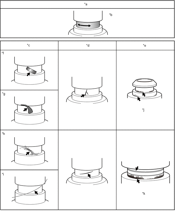
| *a | OK Condition | *b | No damage, foreign matter or corrosion. (Manufacturing marks around the circumference are not the cause of leakage.) |
| *c | Foreign Matter | *d | Damage |
| *e | Corrosion | *f | Metal Fragments |
| *g | Resin Fragments | *h | Lint |
| *i | Hair | *j | White and yellow discoloration (caused by corrosion) |
| *k | Damage (scratches) in axial direction and discoloration (black) | - | - |
9.INSPECT SEALING SURFACE (JOINT AREA)
Check the joint areas of the components for abnormalities.
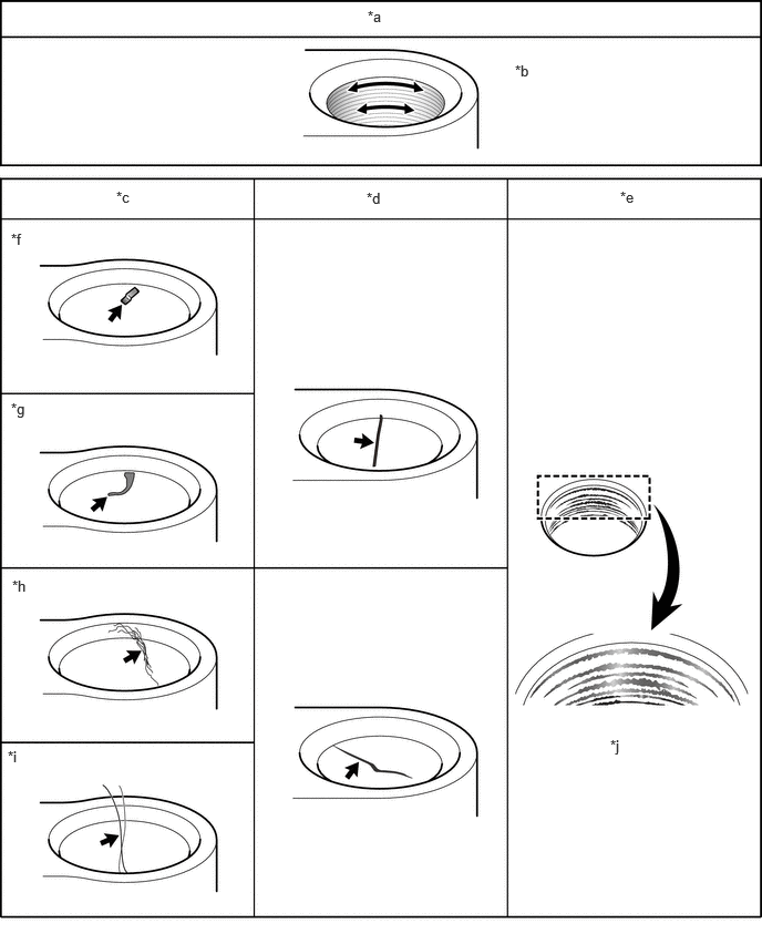
| *a | OK Condition | *b | No damage, foreign matter or corrosion. (Manufacturing marks around the circumference are not the cause of leakage.) |
| *c | Foreign Matter | *d | Damage |
| *e | Corrosion | *f | Metal Fragments |
| *g | Resin Fragments | *h | Lint |
| *i | Hair | *j | Uneven discoloration (black) on sealing face |
10.INSPECT FOR FAULTY EXPANSION VALVE
Recover refrigerant
Connect the refrigerant recovery valve and recover the refrigerant.
- NOTICE:
- ·
Perform this procedure in accordance with the repair manual for each vehicle.
·Use the refrigerant recovery unit in accordance with the manufacturer's instruction manual.
Install air conditioner service tool set
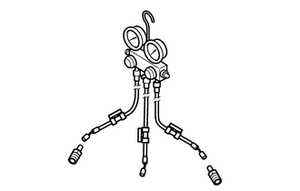
Install the air conditioner service tool set to the vehicle (high pressure side).
- SST
- 09985-20010
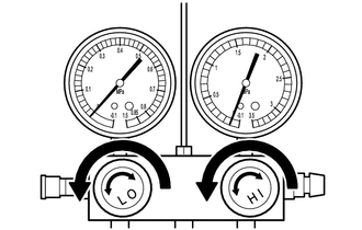
Open all the valves of the air conditioner service tool set.
Install the refrigerant recovery unit or vacuum pump to the vehicle (low pressure side).
| Tool | Connected to |
|---|---|
| Air conditioner service tool set (High pressure hose) | Vehicle (High pressure side) |
| Air conditioner service tool set (Center hose) | - |
| Air conditioner service tool set (Low pressure hose) | - |
| Refrigerant recovery unit or vacuum pump | Vehicle (Low pressure side) |
Inspect expansion valve
Depending on the type of low pressure side hose of the air conditioner service tool set, prevent air from being drawn in as shown in the illustration.
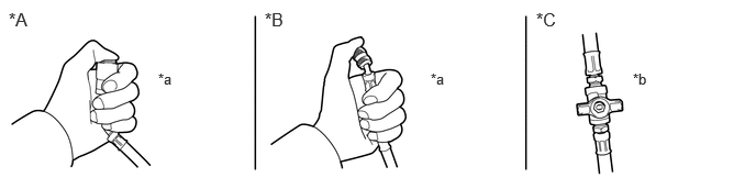
| *A | With Attachment | *B | Without Attachment |
| *C | With Intermediate Valve | - | - |
| *a | Block the end of the hose with your thumb. | *b | Close the intermediate valve. |
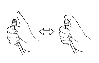
While maintaining the above state, check that the gauge on the low pressure side changes when the center hose is closed and opened as shown in the illustration.
| Result | Judgement |
|---|---|
The gauge indicates a negative pressure (approximately -50 kPa (-0.5 kgf/cm2, -7.3 psi)).
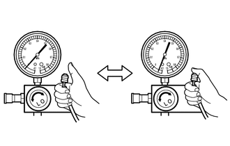
|
Expansion valve is normal. |
The indicated gauge pressure does not change.
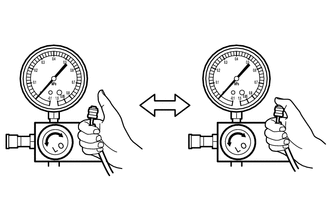
|
Expansion valve is abnormal. |