SUPPLEMENTAL RESTRAINT SYSTEMS AIRBAG SYSTEM(for SFTM Made) SRS Warning Light Remains ON
DESCRIPTION
The SRS warning light is located in the combination meter assembly.
When the SRS is normal, the SRS warning light comes on for approximately 6 seconds after the ignition switch is turned from off to ON, and then goes off automatically.
If there is a malfunction in the SRS, the SRS warning light comes on to inform the driver of a problem.
The SRS is equipped with a voltage-increase circuit (DC-DC converter) in the airbag ECU assembly in case the source voltage drops.
When the auxiliary battery voltage drops, the voltage-increase circuit (DC-DC converter) functions to increase the voltage of the SRS to normal voltage.
A malfunction in this circuit is not recorded in the airbag ECU assembly. The SRS warning light automatically goes off when the source voltage returns to normal.
The signal to illuminate the SRS warning light is transmitted from the airbag ECU assembly to the combination meter assembly through the CAN communication system.
WIRING DIAGRAM
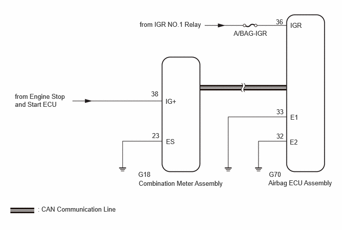
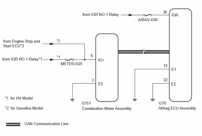
CAUTION / NOTICE / HINT
- NOTICE:
- ·
After the ignition switch is turned off, there may be a waiting time before disconnecting the negative (-) auxiliary battery terminal.
·When disconnecting and reconnecting the auxiliary battery
- HINT:
-
When disconnecting and reconnecting the auxiliary battery, there is an automatic learning function that completes learning when the respective system is used.
·After replacing the airbag ECU assembly, refer to initialization.
·Inspect the fuses for circuits related to this system before performing the following procedure.
·When replacing the combination meter assembly, always replace it with a new one. If a combination meter assembly which was installed to another vehicle is used, the information stored in it will not match the information from the vehicle and a DTC may be stored.
PROCEDURE
Turn the ignition switch to ON and check the SRS warning light condition.
- HINT:
-
The primary check is performed for approximately 6 seconds after the ignition switch is turned to ON.
- Result:
Result Proceed to After the primary check period, the SRS warning light remains on. A After the primary check period, the SRS warning light goes off and comes on again. B
A
B
Measure the auxiliary battery voltage with the ignition switch off.
- Standard voltage:
11 to 14 V
- HINT:
-
It may be possible to tell whether the auxiliary battery is discharged by operating the horn.
-
If the voltage is below 11 V, recharge or replace the auxiliary battery before proceeding to the next step.
- Result:
Proceed to OK NG
OK
NG
Turn the ignition switch off.
Disconnect the cable from the negative (-) auxiliary battery terminal, and wait for at least 60 seconds.
Check that the connector is properly connected to the airbag ECU assembly.
- Result:
Proceed to The connectors are properly connected The connectors are not properly connected
The connectors are properly connected
The connectors are not properly connected
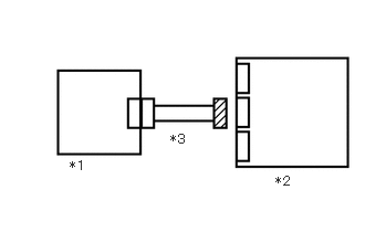
| *1 | Combination Meter Assembly |
| *2 | Airbag ECU Assembly |
| *3 | Wire Harness |
Disconnect the airbag ECU assembly connector.
Check that the connectors (on the airbag ECU assembly side) are not damaged.
- Result:
Proceed to The connectors are not deformed or damaged The connectors are deformed or damaged
The connectors are not deformed or damaged
The connectors are deformed or damaged
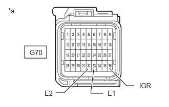
| *a | Front view of wire harness connector
(to Airbag ECU Assembly) |
Connect the cable to the negative (-) auxiliary battery terminal, and wait for at least 2 seconds.
Turn the ignition switch to ON.
Operate all components of the electrical systems (defogger, wipers, headlights, heater blower, etc.).
Measure the voltage according to the value(s) in the table below.
- Standard Voltage:
Tester Connection Switch Condition Specified Condition G70-36 (IGR) - Body ground Ignition switch ON 8 to 16 V
Turn the ignition switch off.
Measure the resistance according to the value(s) in the table below.
- Standard Resistance:
Tester Connection Condition Specified Condition G70-33 (E1) - Body ground Always Below 1 Ω G70-32 (E2) - Body ground Always Below 1 Ω
- Result:
Proceed to OK NG
OK
NG
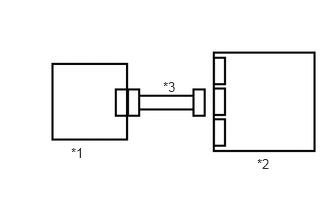
| *1 | Combination Meter Assembly |
| *2 | Airbag ECU Assembly |
| *3 | Wire Harness |
Turn the ignition switch to ON.
Approximately 6 seconds after the ignition switch to ON, check the condition of the SRS warning light.
- Result:
Proceed to Turns off for 10 seconds, and then illuminates Turns off for 10 seconds, and then remains off
Turns off for 10 seconds, and then illuminates
Turns off for 10 seconds, and then remains off
Check if a CAN communication DTC is output.
for HV Model: Click herePower Source / Network>NETWORKING>CAN COMMUNICATION SYSTEM (for SFTM Made HV Model)>DIAGNOSIS SYSTEM202405,999999,_57,_083091,_0694853,RM100000002LUHO,
for Gasoline Model: Click herePower Source / Network>NETWORKING>CAN COMMUNICATION SYSTEM (for SFTM Made Gasoline Model)>DIAGNOSIS SYSTEM202405,999999,_57,_083091,_0694854,RM100000002LVP6,
- Result:
Proceed to DTCs are output DTC is not output
DTCs are output
for HV Model: Click herePower Source / Network>NETWORKING>CAN COMMUNICATION SYSTEM (for SFTM Made HV Model)>HOW TO PROCEED WITH TROUBLESHOOTING202409,999999,_57,_083091,_0694853,RM100000002NT0M,
for Gasoline Model: Click herePower Source / Network>NETWORKING>CAN COMMUNICATION SYSTEM (for SFTM Made Gasoline Model)>HOW TO PROCEED WITH TROUBLESHOOTING202409,999999,_57,_083091,_0694854,RM100000002NUBH,
DTC is not output
Measure the auxiliary battery voltage with the ignition switch off.
- Standard voltage:
11 to 14 V
- HINT:
-
It may be possible to tell whether the auxiliary battery is discharged by operating the horn.
-
If the voltage is below 11 V, recharge or replace the auxiliary battery before proceeding to the next step.
- Result:
Proceed to OK NG
OK
NG
Turn the ignition switch off.
Disconnect the cable from the negative (-) auxiliary battery terminal, and wait for at least 60 seconds.
Check that the connector is properly connected to the combination meter assembly and airbag ECU assembly.
- Result:
Proceed to The connectors are properly connected The connectors are not properly connected
The connectors are properly connected
The connectors are not properly connected
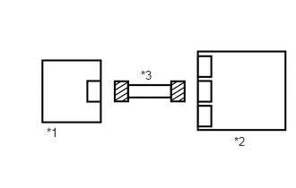
| *1 | Combination Meter Assembly |
| *2 | Airbag ECU Assembly |
| *3 | Wire Harness |
Disconnect the airbag ECU assembly connector.
Disconnect the combination meter assembly connector.
Check that the connectors (on the combination meter assembly side and airbag ECU assembly side) are not damaged.
- Result:
Proceed to The connectors are not deformed or damaged The connectors are deformed or damaged
The connectors are not deformed or damaged
The connectors are deformed or damaged
| *a | Front view of wire harness connector
(to Airbag ECU Assembly) |
Connect the cable to the negative (-) auxiliary battery terminal.
Turn the ignition switch to ON.
Operate all components of the electrical systems (defogger, wipers, headlights, heater blower, etc.).
Measure the voltage according to the value(s) in the table below.
- Standard Voltage:
Tester Connection Switch Condition Specified Condition G70-36 (IGR) - Body ground Ignition switch ON 8 to 16 V
Turn the ignition switch off.
Measure the resistance according to the value(s) in the table below.
- Standard Resistance:
Tester Connection Condition Specified Condition G70-33 (E1) - Body ground Always Below 1 Ω G70-32 (E2) - Body ground Always Below 1 Ω
- Result:
Proceed to OK NG
OK
NG
Check the vehicle type.
- Result:
Result Proceed to for 7 Inch Multi-information Display A for 12.3 Inch Multi-information Display B
A
B
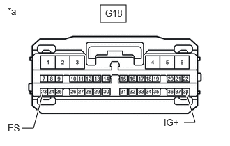
| *a | Front view of wire harness connector
(to Combination Meter Assembly) |
Measure the voltage according to the value(s) in the table below.
- Standard Voltage:
Tester Connection Switch Condition Specified Condition G18-38 (IG+) - Body ground Ignition switch ON 10.5 to 16 V
Measure the voltage according to the value(s) in the table below.
Turn the ignition switch off.
Measure the resistance according to the value(s) in the table below.
- Standard Resistance:
Tester Connection Condition Specified Condition G18-23 (ES) - Body ground Always Below 1 Ω
- Result:
Proceed to OK NG
OK
NG
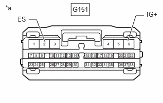
| *a | Front view of wire harness connector
(to Combination Meter Assembly) |
Measure the voltage according to the value(s) in the table below.
- Standard Voltage:
for HV Model Tester Connection Switch Condition Specified Condition G151-6 (IG+) - Body ground Ignition switch ON 11 to 14 V
for Gasoline Model Tester Connection Switch Condition Specified Condition G151-6 (IG+) - Body ground Ignition switch ON 10.5 to 16 V
Turn the ignition switch off.
Measure the resistance according to the value(s) in the table below.
- Standard Resistance:
Tester Connection Condition Specified Condition G151-2 (ES) - Body ground Always Below 1 Ω
- Result:
Proceed to OK NG (for Gasoline Model) NG (for HV Model)
OK
NG (for Gasoline Model)
NG (for HV Model)
| *1 | Combination Meter Assembly |
| *2 | Airbag ECU Assembly |
| *3 | Wire Harness |
Disconnect the cable from the negative (-) auxiliary battery terminal, and wait for at least 60 seconds.
Connect the G18*1 or G151*2 combination meter assembly connector.
*1: for 7 Inch Multi-information Display
*2: for 12.3 Inch Multi-information Display
Connect the cable to the negative (-) auxiliary battery terminal.
Approximately 6 seconds after the ignition switch to ON, check the condition of the SRS warning light.
- Result:
Proceed to Turns off for 10 seconds, and then illuminates Turns off for 10 seconds, and then remains off
Turns off for 10 seconds, and then illuminates
Turns off for 10 seconds, and then remains off