NETWORKING CAN COMMUNICATION SYSTEM(for SFTM Made Gasoline Model) DIAGNOSIS SYSTEM
Description of "Communication Bus Check" Screen
- NOTICE:
-
The following communication bus check screen is provided only as an example. This screen differs from the actual screen for this vehicle.
- HINT:
-
The ECUs and sensors that are normally connected to the CAN communication system are displayed on the GTS.
Select "Communication Bus Check" on the menu screen of the GTS.
- CAN Bus Check
- 50007
- HINT:
-
If items are not selected correctly in the vehicle specification pop up screen, the name of the CAN junction connector to which the ECUs or sensors are connected may not be displayed on the "Communication Bus Check" screen.
Confirm that the "Communication Bus Check" screen is displayed and the ECUs and sensors that are normally connected to the CAN communication system are displayed.
- HINT:
- ·
Even if an ECU or sensor that is connected to a bus that is monitored by a bus monitoring ECU (gateway function equipped ECU) is not communicating, it will remain displayed on the "Communication Bus Check" screen.
·When an ECU or sensor that is connected to a bus that is not monitored by a bus monitoring ECU (gateway function equipped ECU) is not displayed on the "Communication Bus Check" screen, it means that it is not communicating.
The default display setting selected on the combo box is ALL. When checking for ECUs or sensors for a specific bus, choose the bus from the drop down list. ALL, each bus, each sub bus and Central Gateway are listed in the drop down list.
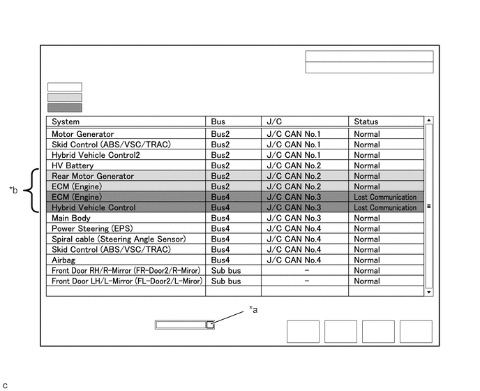
| *a | Combo box | *b | Background color is red or yellow |
| Item | Detail |
|---|---|
| Combo box: ALL | Displays all ECUs and sensors connected to the central bus and sub buses. |
| Combo box: Bus | Displays ECUs and sensors connected to the selected bus. |
| Combo box: Sub bus | Displays ECUs and sensors connected to the selected sub bus. |
| Combo box: Central Gateway | Displays all ECUs and sensors connected to the central bus. |
- NOTICE:
- ·
When using the combo box, it may be possible to select a sub bus from the drop down list that does not have any connected ECUs or sensors. This is not a malfunction and occurs when there is no optional device connected to a sub bus which is monitored by a sub bus monitoring ECU (gateway function equipped ECU).
·In the drop down list, all sub buses applicable to the model are displayed (e.g. LIN communication sub buses are also displayed). For information on sub buses necessary to diagnose the CAN communication system, refer to System Diagram.
- HINT:
-
The background color of an ECU or sensor changes according to its connection status as indicated in the following table.
Description of "Communication Bus Check" Screen Bus Type Background Color Connection Status Bus White Communication has been normal. Yellow Communication stop occurred at least once since the start of the CAN bus check, but communication is currently occurring (unstable communication). Red Currently not communicating (either of the following):
·Not communicating since the start of the CAN bus check
·Communication occurred at least once since the start of the CAN bus check, but is currently not occurring.
Not displayed Either of the following:
·The central gateway ECU (network gateway ECU) has an internal malfunction or cannot communicate with the GTS.*4
·No ECUs or sensors are connected to the bus.*5
Sub bus with a gateway function equipped ECU that does not memorize connected ECUs or sensors*2 White Communication has been normal since the start of the CAN bus check. Yellow Communication stop occurred at least once since the start of the CAN bus check, but communication is currently occurring (unstable communication). Red Communication occurred at least once since the start of the CAN bus check, but is currently not occurring. Not displayed Communication stop has continued since the start of the CAN bus check.*1 Sub bus with a gateway function equipped ECU that memorizes connected ECUs and sensors*3 White Communication has been normal. Yellow Communication stop occurred at least once since the start of the CAN bus check, but communication is currently occurring (unstable communication). Red Currently not communicating (either of the following):
·Not communicating since the start of the CAN bus check
·Communication occurred at least once since the start of the CAN bus check, but is currently not occurring.
Not displayed Either of the following:
·The gateway function equipped ECU cannot communicate with the central gateway ECU.*6
·No ECUs or sensors are connected to the sub bus.*7
- ·
Gateway function equipped ECUs relay signals between ECUs and sensors connected to different buses.
·*1: An ECU or sensor is installed to the vehicle but is not displayed on the "Communication Bus Check" screen.
·*2: the gateway function equipped ECU does not memorize ECUs and sensors connected to its respective sub bus.
·*3: the gateway function equipped ECU memorizes ECUs and sensors connected to its respective sub bus.
·*4: When the central gateway ECU (network gateway ECU) has an internal malfunction or cannot communicate with the GTS, the name of buses, sub buses, ECUs and sensors will not be displayed.
·*5: When no ECUs or sensors are connected to a bus, the message "There is no system found on the communication Bus." will be displayed.
·*6: When a gateway function equipped ECU cannot communicate with the central gateway ECU (network gateway ECU), the name of sub buses and ECUs or sensors connected to the sub bus will not be displayed.
·*7: When no ECUs or sensors are connected to the sub bus, the message "There is no system found on the communication Bus." will be displayed.
·If there is no communication between the GTS and the vehicle, or no ECUs or sensors are displayed as connected, check the central gateway ECU (network gateway ECU) and diagnosis bus (The bus that connects the DLC3 to the central gateway ECU (network gateway ECU)) for malfunctions.
Monitor the screen for any ECU or sensor connection status changes for a period of 2 minutes.
- HINT:
- ·
If an open occurs in one of the wires of a CAN branch line, it may interfere with the communication of other ECUs or sensors resulting in an incorrect state being displayed.
·If the connection status changes intermittently during the inspection, repair the open in the branch line of the ECU or sensor that is not communicating, and then perform Communication Bus Check again.
Description of "Communication Bus Check (Detail)" Screen
- NOTICE:
-
The following communication bus check screen is provided only as an example. This screen differs from the actual screen for this vehicle.
- HINT:
-
The communication error history of ECUs or sensors which have communication error history can be displayed on the "Communication Bus Check (Detail)" screen.
Select "Communication Bus Check" on the menu screen of the GTS.
- CAN Bus Check
- 50007
- HINT:
-
If items are not selected correctly in the vehicle specification pop up screen, the name of the CAN junction connector to which the ECUs or sensors are connected may not be displayed on the "Communication Bus Check" screen.
Select "Detail" on the "Communication Bus Check" screen.
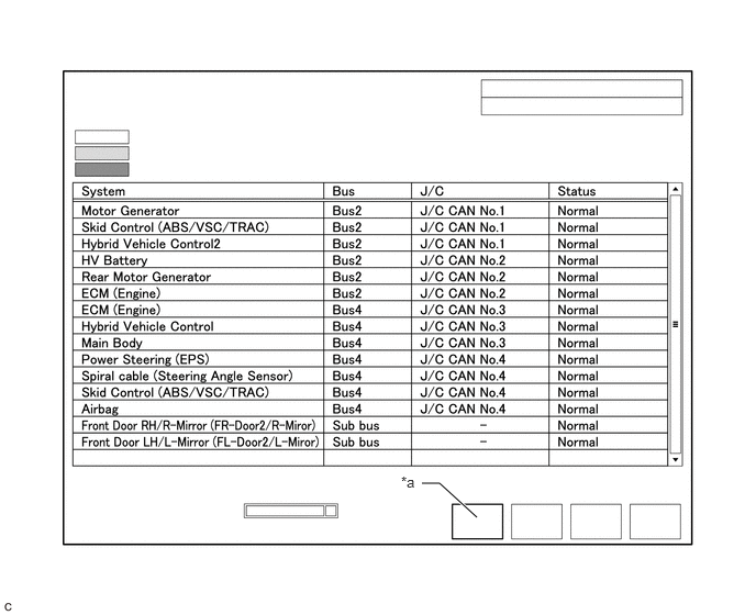
| *a | Communication Bus Check (Detail) | - | - |
Confirm that the "Communication Bus Check (Detail)" screen is displayed and the communication error history of the ECUs or sensors up to present is displayed.
- HINT:
- ·
Lost Communication Time and Lost Communication Trip are only displayed for the central bus.
·Lost Communication Time and Lost Communication Trip are not displayed for sub buses.
The default display setting selected on the combo box is ALL. When checking for ECUs or sensors for a specific bus, choose the bus from the drop down list. ALL, each bus, each sub bus and Central Gateway are listed in the drop down list.
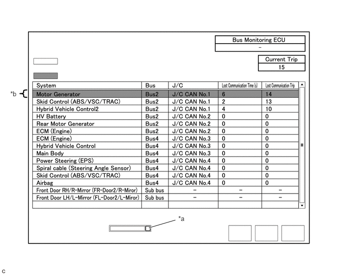
| *a | Combo box | *b | Background color is red |
| Item | Detail |
|---|---|
| Combo box: ALL | Displays all ECUs and sensors connected to the central bus and sub buses. |
| Combo box: Bus | Displays ECUs and sensors connected to the selected bus. |
| Combo box: Sub bus | Displays ECUs and sensors connected to the selected sub bus. |
| Combo box: Central Gateway | Displays all ECUs and sensors connected to the central bus. |
| Bus Monitoring ECU | Displays the gateway function equipped ECU which monitors the selected bus or sub bus. |
| Current Trip | Displays the total number of trips up to now* |
| Lost Communication Time(s) | Displays the longest period of time in seconds that the ECU or sensor connected to the central bus was not communicating. |
| Lost Communication Trip | Displays the trip in which the longest period of time that the ECU or sensor connected to the central bus was not communicating occurred. |
*: If the component has been replaced with a new one, the total number of trips after the replacement is displayed.
- NOTICE:
- ·
The Lost Communication Time column displays the longest period of time in seconds that the central gateway ECU (network gateway ECU) detected a communication stop in the respective ECU or sensor.
·The Lost Communication Trip column displays the trip in which the central gateway ECU (network gateway ECU) detected the longest communication stop in the respective ECU or sensor.
·When using the combo box, it may be possible to select a sub bus from the drop down list that does not have any connected ECUs or sensors. This is not a malfunction and occurs when there is no optional device connected to a sub bus which is monitored by a sub bus monitoring ECU (gateway function equipped ECU).
·In the drop down list, all sub buses applicable to the model are displayed (e.g. LIN communication sub buses are also displayed). For information on sub buses necessary to diagnose CAN communication system, refer to the System Diagram.
- HINT:
-
The background color of an ECU or sensor changes according to its connection status as indicated in the following table.
Description of "Communication Bus Check (Detail)" Screen Bus Type Background Color Connection Status Bus White Either of the following:
·Communication has been normal.
·Lost Communication Time is below 6 seconds.
Red Lost Communication Time is 6 seconds or more. Not displayed Either of the following:
·The central gateway ECU (network gateway ECU) has an internal malfunction or cannot communicate with the GTS.*1
·No ECUs or sensors are connected to the bus.*2
Sub bus White Lost Communication Time is displayed as "-". Not displayed Either of the following:
·The gateway function equipped ECU cannot communicate with the central gateway ECU.*3
·No ECUs or sensors are connected to the sub bus.*4
- ·
If there is no communication between the GTS and the vehicle, or no ECUs or sensors are displayed as connected, check the central gateway ECU (network gateway ECU) and diagnosis bus (The bus that connects the DLC3 to the central gateway ECU (network gateway ECU)) for malfunctions.
·Lost Communication Time and Lost Communication Trip are not displayed for sub buses.
·*1: When the central gateway ECU (network gateway ECU) has an internal malfunction or cannot communicate with the GTS, the name of buses, sub buses, ECUs and sensors will not be displayed.
·*2: When no ECUs or sensors are connected to a bus, the message "There is no system found on the communication Bus." will be displayed.
·*3: When a gateway function equipped ECU cannot communicate with the central gateway ECU (network gateway ECU), the name of sub buses and ECUs or sensors connected to the sub bus will not be displayed.
·*4: When no ECUs or sensors are connected to the sub bus, the message "There is no system found on the communication Bus." will be displayed.
Communication Bus Check (Communication Malfunction Check)
- HINT:
-
DTCs related to CAN communication are displayed for each ECU on the GTS.
Select "Communication Bus Check" on the menu screen of the GTS.
- CAN Bus Check
- 50007
Select "Communication Malfunction Check" on the "Communication Bus Check" screen.
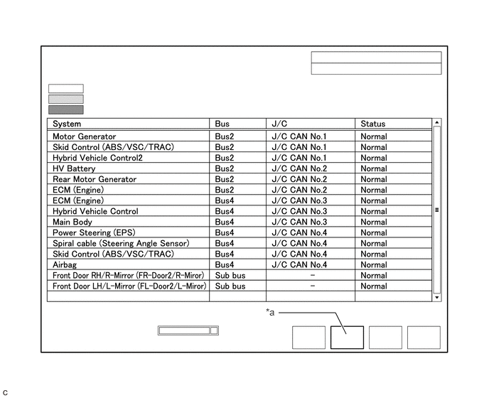
| *a | Communication Malfunction Check | - | - |
Confirm that the "Communication Malfunction Check" screen is displayed and CAN communication DTCs for each ECU are displayed.
- HINT:
-
When there are no CAN communication DTCs stored, no DTCs will be displayed.
How to Use "Communication Bus Check" Screen in Inspection
- NOTICE:
-
The following CAN bus wiring diagram or communication bus check screen is provided only as an example. This wiring diagram or screen differs from the actual one for this vehicle.
- HINT:
- ·
If the CAN communication system is currently malfunctioning, it is recommended to use Communication Bus Check rather than Communication DTCs for determining the suspected area.
·Turn the ignition switch to ON, or perform the necessary operations to reproduce the problem symptom, select "Communication Bus Check" and wait approximately 2 minutes. Check the communication status of each ECU or sensor on the screen while performing this operation.
If the CAN communication system is currently malfunctioning, determine the suspected area through Communication Bus Check as follows:
| Problem Symptom Pattern | Display on Communication Bus Check Screen | Suspected Area |
|---|---|---|
| A | Almost all of the ECUs and sensors connected to the malfunctioning CAN bus are displayed as not communicating on the "Communication Bus Check" screen. | ·
Short between CAN bus lines (CANH and CANL) ·
Short to +B in a CAN bus line (CANH or CANL) ·
Short to ground in a CAN bus line (CANH or CANL) |
| B | ECUs or sensors farther from the central gateway ECU (network gateway ECU) than the open in the wires are displayed as not communicating on the "Communication Bus Check" screen. | Open in both wires of a main bus line in the central bus |
| C | One ECU or sensor is displayed as not communicating on the "Communication Bus Check" screen. | ·
Open in both wires of a branch line connected to an ECU or sensor in the central bus ·
Internal malfunction of an ECU or sensor in the central bus ·
Malfunction in the power supplied to an ECU or sensor in the central bus |
| D | No ECUs or sensors are displayed on the "Communication Bus Check" screen. | ·
Internal malfunction of the central gateway ECU (network gateway ECU) ·
Malfunction in the power supplied to the central gateway ECU (network gateway ECU) ·
Open in both wires of the branch line in the diagnosis bus (DLC3 - Central gateway ECU (network gateway ECU)) ·
Short between CAN bus lines (CANH and CANL) in the diagnosis bus (DLC3 - Central gateway ECU (network gateway ECU)) ·
Short to +B in a CAN bus line (CANH or CANL) in the diagnosis bus (DLC3 - Central gateway ECU (network gateway ECU)) ·
Short to ground in a CAN bus line (CANH or CANL) in the diagnosis bus (DLC3 - Central gateway ECU (network gateway ECU)) |
| E | One ECU or sensor is displayed as not communicating in multiple buses on the "Communication Bus Check" screen. | ·
Internal malfunction of an ECU or sensor connected to multiple buses ·
Malfunction in the power supplied to an ECU or sensor connected to multiple buses |
| F | Some ECUs or sensors are displayed as not communicating in the central bus and other ECUs or sensors are displayed as not communicating in a sub bus. | ·
Open in a wire of a branch line connected to an ECU or sensor in the central bus ·
Internal malfunction of an ECU or sensor in the central bus |
| G | A gateway function equipped ECU is displayed as not communicating in the central bus and ECUs and sensors connected to its respective sub bus are not displayed. | ·
Open in both wires of a branch line connected to a gateway function equipped ECU ·
Internal malfunction of a gateway function equipped ECU ·
Malfunction in the power supplied to a gateway function equipped ECU |
| H | One ECU or sensor is displayed as not communicating in a sub bus on the "Communication Bus Check" screen. | ·
Open in both wires of a branch line connected to an ECU or sensor in a sub bus ·
Internal malfunction of an ECU or sensor in a sub bus ·
Malfunction in the power supplied to an ECU or sensor in a sub bus |
| I | ECUs or sensors farther from the sub bus monitoring ECU (gateway function equipped ECU) than the open in the wires are displayed as not communicating on the "Communication Bus Check" screen. | Open in both wires of a main bus line in a sub bus |
Problem Symptom Pattern A
| Details of Malfunction | ·
Short between CAN bus lines (CANH and CANL) in Bus 2 ·
Short to +B in a CAN bus line (CANH or CANL) in Bus 2 ·
Short to ground in a CAN bus line (CANH or CANL) in Bus 2 |
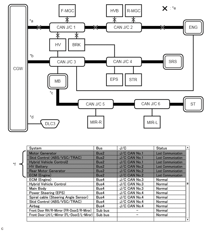
| *a | Bus 2 | *b | Bus 4 |
| *c | Sub bus | *d | Diagnosis bus |
| *e | Location of malfunction | *f | Background color is red |
- HINT:
- ·
Due to the malfunction, almost all of the ECUs and sensors connected to Bus 2 will be displayed as not communicating and their background color will be red.
·The malfunction in Bus 2 will not affect the other buses.
·The malfunctioning part can be determined by inspecting for an open in the main bus line, a short between bus lines or a short to +B or ground.
·Make sure to perform the inspection to measure resistances of buses to determine the cause of the malfunction.
| Details of Malfunction | ·
Short between CAN bus lines (CANH and CANL) in Bus 4 ·
Short to +B in a CAN bus line (CANH or CANL) in Bus 4 ·
Short to ground in a CAN bus line (CANH or CANL) in Bus 4 |
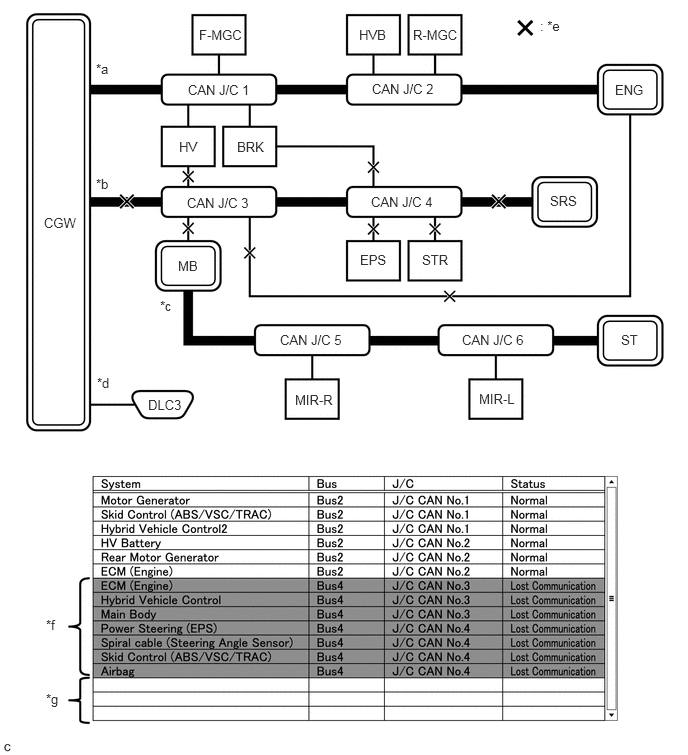
| *a | Bus 2 | *b | Bus 4 |
| *c | Sub bus | *d | Diagnosis bus |
| *e | Location of malfunction | *f | Background color is red |
| *g | Not displayed | - | - |
- HINT:
- ·
Due to the malfunction, almost all of the ECUs and sensors connected to Bus 4 will be displayed as not communicating and their background color will be red.
·The malfunction will not affect the other buses of the central bus. However, the sub bus connected to Bus 4 is likely to be affected. the gateway function equipped ECU connected to Bus 4 will not communicate and consequently the sub bus and its respective ECUs or sensors monitored by the gateway function equipped ECU (sub bus monitoring ECU) will not be displayed, indicating that the gateway function equipped ECU is not communicating with the central gateway ECU (network gateway ECU).
·The malfunctioning part can be determined by inspecting for an open in the main bus line, a short between bus lines or a short to +B or ground.
·Make sure to perform the inspection to measure resistances of buses to determine the cause of the malfunction.
Problem Symptom Pattern B
| Details of Malfunction | Open in both wires of the main bus line between the CGW and No. 1 CAN junction connector in Bus 2 |
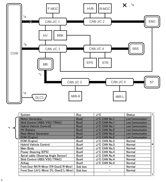
| *a | Bus 2 | *b | Bus 4 |
| *c | Sub bus | *d | Diagnosis bus |
| *e | Location of malfunction | *f | Background color is red |
- HINT:
- ·
Due to the malfunction, almost all of the ECUs and sensors connected to Bus 2 will be displayed as not communicating and their background color will be red.
·The malfunction in Bus 2 will not affect the other buses.
·The malfunctioning part can be determined by inspecting for an open in the main bus line.
·Make sure to perform the inspection to measure resistances of buses to determine the cause of the malfunction.
| Details of Malfunction | Open in both wires of the main bus line between the No. 1 CAN junction connector and No. 2 CAN junction connector in Bus 2 |
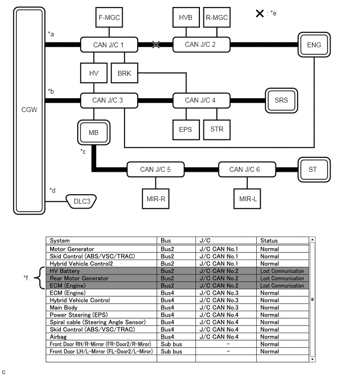
| *a | Bus 2 | *b | Bus 4 |
| *c | Sub bus | *d | Diagnosis bus |
| *e | Location of malfunction | *f | Background color is red |
- HINT:
- ·
Due to the malfunction, ECUs or sensors farther from the CGW than the open in the wires will be displayed as not communicating and their background color will be red.
·The malfunction in Bus 2 will not affect the other buses.
·The malfunctioning part can be determined by inspecting for an open in the main bus line.
·Make sure to perform the inspection to measure resistances of buses to determine the cause of the malfunction.
| Details of Malfunction | Open in both wires of the main bus line between the No. 2 CAN junction connector and ENG in Bus 2 |
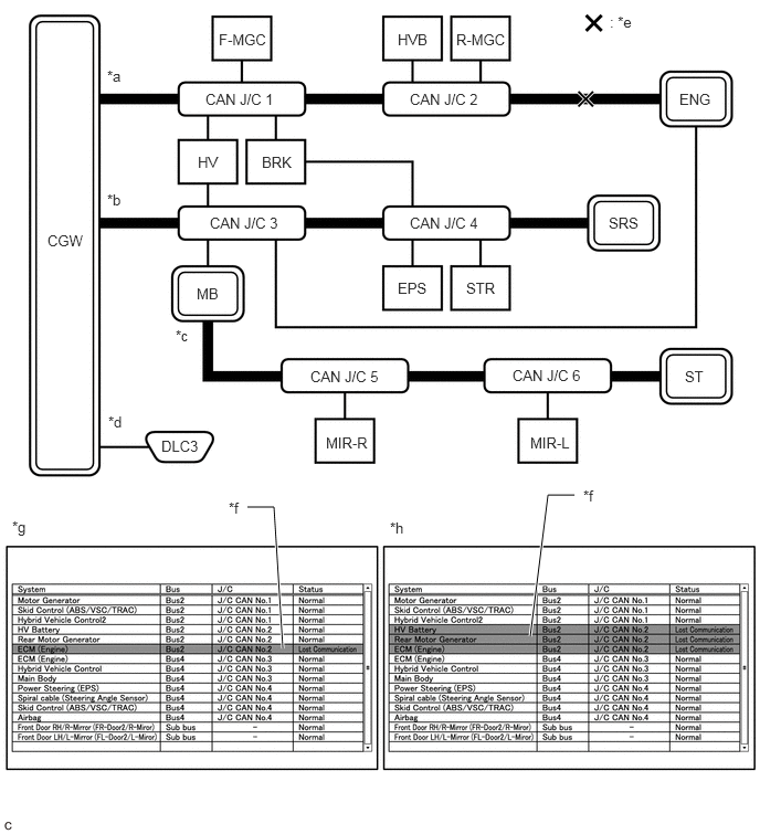
| *a | Bus 2 | *b | Bus 4 |
| *c | Sub bus | *d | Diagnosis bus |
| *e | Location of malfunction | *f | Background color is red |
| *g | Pattern 1 | *h | Pattern 2 |
- HINT:
- ·
Even when the same part of the main bus line is open, depending on internal electrical noise which changes according to the position of the open in the line, the information displayed on the "Communication Bus Check" screen may differ.
·In pattern 2, the information displayed may be the same as when there is an open in both wires in the main bus line between the No. 1 CAN junction connector and No. 2 CAN junction connector, which may make it difficult to determine the malfunctioning part.
·The malfunction in Bus 2 will not affect the other buses.
·Make sure to perform the inspection to measure resistances of buses to determine the cause of the malfunction.
Problem Symptom Pattern C
| Details of Malfunction | Open in both wires of the branch line connected to F-MGC in Bus 2 |
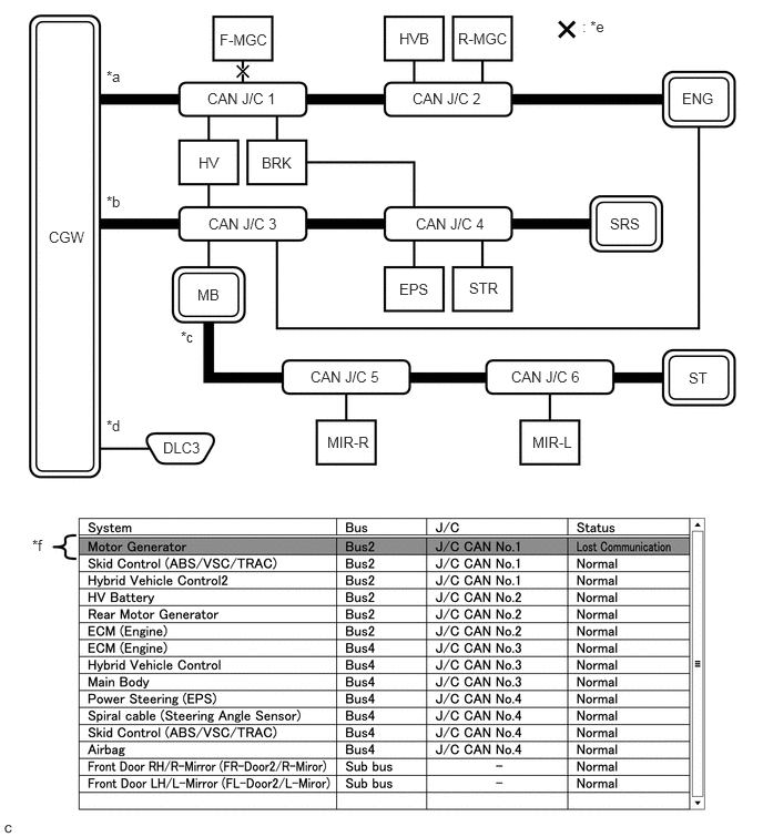
| *a | Bus 2 | *b | Bus 4 |
| *c | Sub bus | *d | Diagnosis bus |
| *e | Location of malfunction | *f | Background color is red |
- HINT:
-
The information displayed on the "Communication Bus Check" screen will be the same for an open in both wires of a branch line, an internal malfunction of an ECU or sensor or a malfunction in the power supplied to an ECU or sensor. In this example, the background color of the malfunctioning ECU or sensor will be red.
| Details of Malfunction | ·
Internal malfunction of F-MGC in Bus 2 ·
Malfunction in the power supplied to F-MGC in Bus 2 |
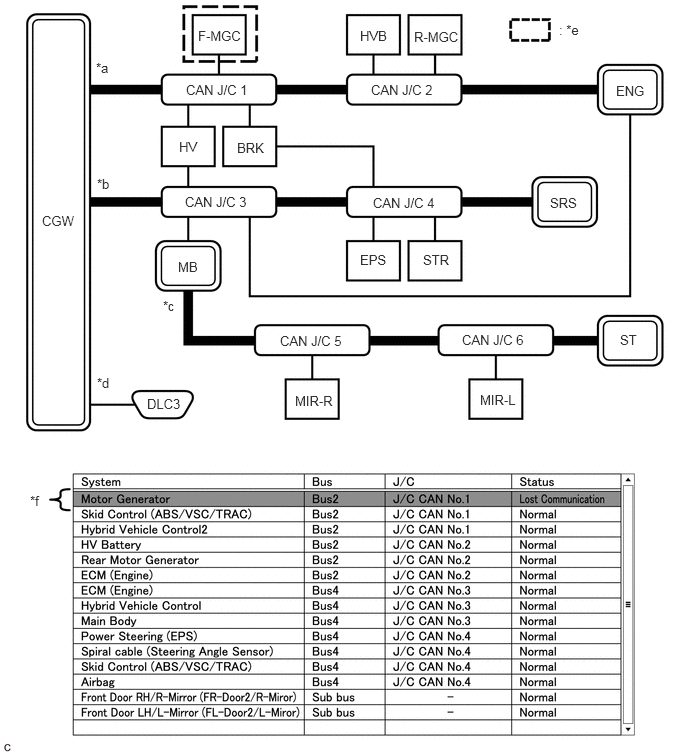
| *a | Bus 2 | *b | Bus 4 |
| *c | Sub bus | *d | Diagnosis bus |
| *e | Location of malfunction | *f | Background color is red |
- HINT:
-
The information displayed on the "Communication Bus Check" screen will be the same for an open in both wires of a branch line, an internal malfunction of an ECU or sensor or a malfunction in the power supplied to an ECU or sensor. In this example, the background color of the malfunctioning ECU or sensor will be red.
| Details of Malfunction | Open in both wires of the branch line connected to ENG in Bus 4 |
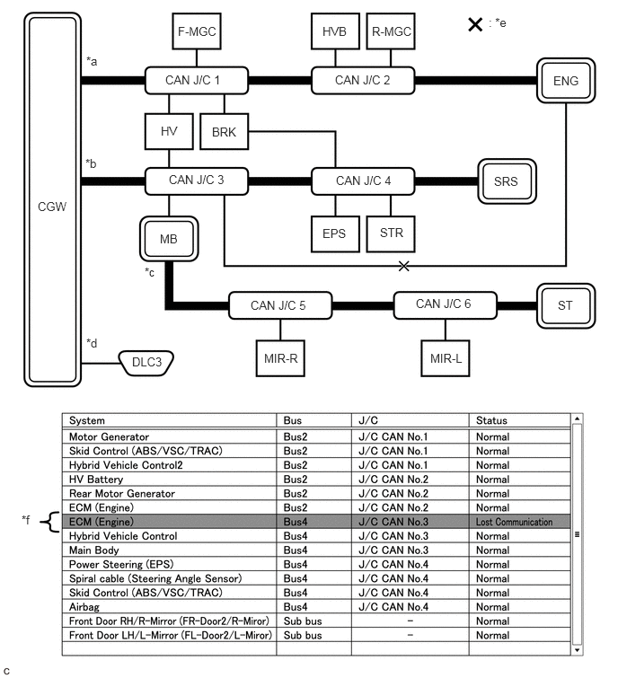
| *a | Bus 2 | *b | Bus 4 |
| *c | Sub bus | *d | Diagnosis bus |
| *e | Location of malfunction | *f | Background color is red |
- HINT:
- ·
The malfunction in Bus 4 will not affect the other buses.
·Due to the malfunction, although ENG is communicating normally with CGW via Bus 2, it is not communicating with CGW via Bus 4. Consequently, it will be displayed as not communicating in Bus 4.
Problem Symptom Pattern D
| Details of Malfunction | ·
Internal malfunction of the CGW ·
Malfunction in the power supplied to the CGW |
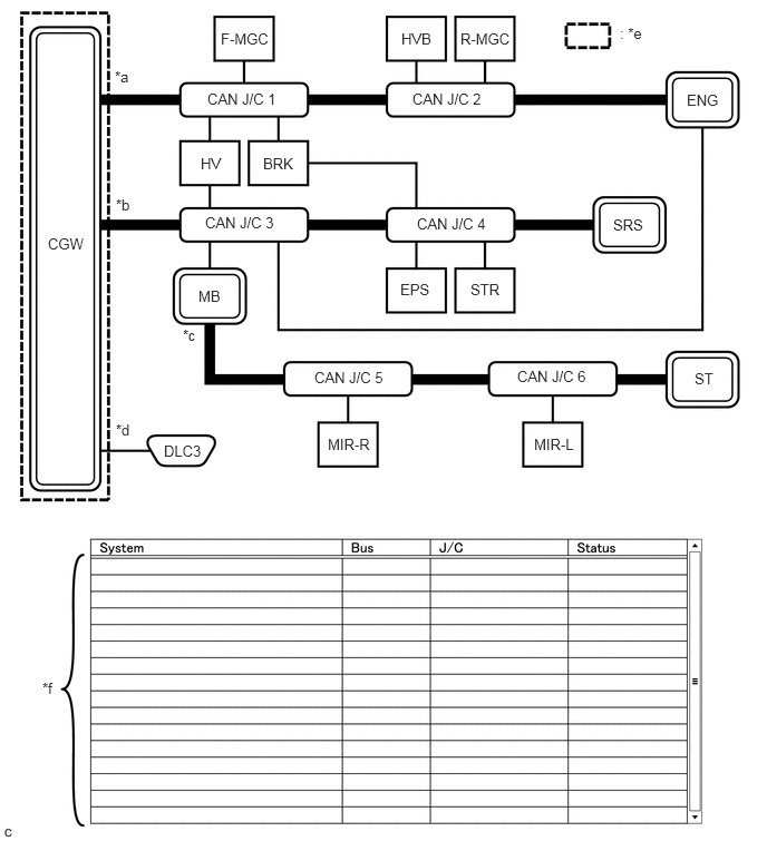
| *a | Bus 2 | *b | Bus 4 |
| *c | Sub bus | *d | Diagnosis bus |
| *e | Location of malfunction | *f | Not displayed |
- HINT:
-
When there is no communication between the GTS and the vehicle, no ECUs or sensors will be displayed.
| Details of Malfunction | Open in both wires of the branch lines in the diagnosis bus |
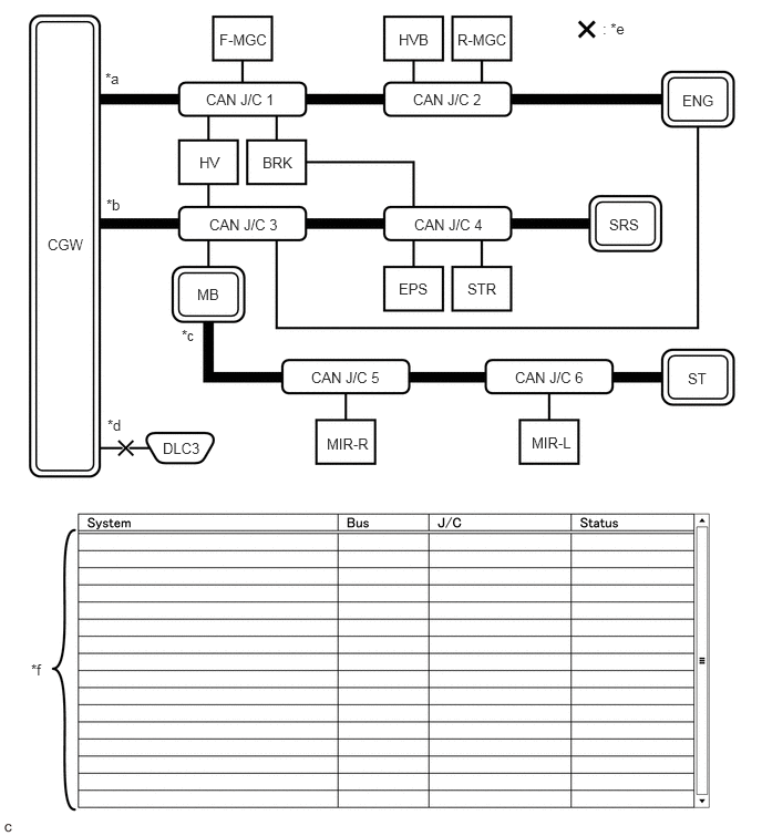
| *a | Bus 2 | *b | Bus 4 |
| *c | Sub bus | *d | Diagnosis bus |
| *e | Location of malfunction | *f | Not displayed |
- HINT:
-
When there is no communication between the GTS and the vehicle, no ECUs or sensors will be displayed.
Problem Symptom Pattern E
| Details of Malfunction | ·
Internal malfunction of BRK ·
Malfunction in the power supplied to BRK |
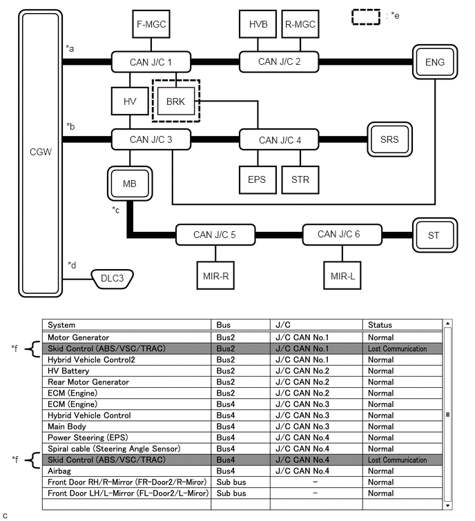
| *a | Bus 2 | *b | Bus 4 |
| *c | Sub bus | *d | Diagnosis bus |
| *e | Location of malfunction | *f | Background color is red |
- HINT:
-
The information displayed on the "Communication Bus Check" screen will be the same for an internal malfunction of an ECU or sensor, or a malfunction in the power supplied to an ECU or sensor.
-
Due to the malfunction, BRK is not communicating with the CGW via both Bus 2 and Bus 4. Consequently, the background color of BRK will be red for both Bus 2 and Bus 4.
Problem Symptom Pattern F
| Details of Malfunction | ·
Open in a wire of the branch line connected to HV in Bus 4 ·
Internal malfunction of HV in Bus 4 |
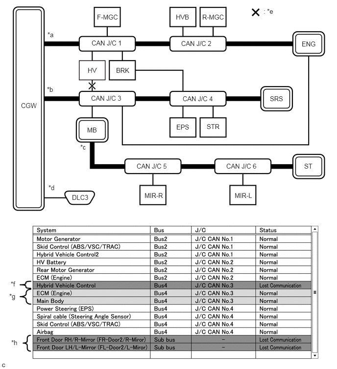
| *a | Bus 2 | *b | Bus 4 |
| *c | Sub bus | *d | Diagnosis bus |
| *e | Location of malfunction | *f | Background color is red |
| *g | Background color intermittently becomes yellow or red | *h | Not displayed or background color is yellow or red |
- HINT:
- ·
In the "Communication Bus check" screen shown in the illustration, electrical noise in the CAN bus caused by an open in a wire in the branch line connected to HV interferes with the communication of MB causing unstable communication. Also, since MB is a gateway function equipped ECU, communication of ECUs connected to its respective sub bus will also be unstable.
·In the "Communication Bus Check" screen shown in the illustration, because the background color of HV is red, it is suspected that HV is the most likely cause of the malfunction. Therefore, it is suspected that HV is not communicating.
Problem Symptom Pattern G
| Details of Malfunction | ·
Open in both wires of the branch line connected to MB in Bus 4 ·
Internal malfunction of MB in Bus 4 ·
Malfunction in the power supplied to MB in Bus 4 |
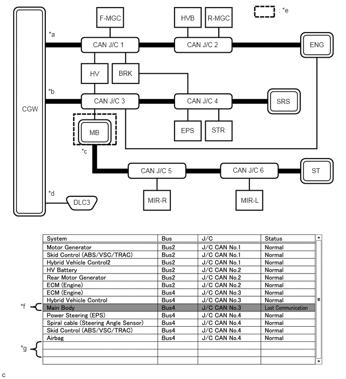
| *a | Bus 2 | *b | Bus 4 |
| *c | Sub bus | *d | Diagnosis bus |
| *e | Location of malfunction | *f | Background color is red |
| *g | Not displayed | - | - |
- HINT:
- ·
If there is a communication malfunction in a gateway function equipped ECU, ECUs connected to its respective sub bus will also be affected and will not be displayed.
·In the "Communication Bus Check" screen shown in the illustration, MB is a gateway function equipped ECU. Therefore, MB is suspected as not communicating.
Problem Symptoms Pattern H
| Details of Malfunction | ·
Internal malfunction of MIR-L in the sub bus ·
Malfunction in the power supplied to MIR-L in the sub bus |
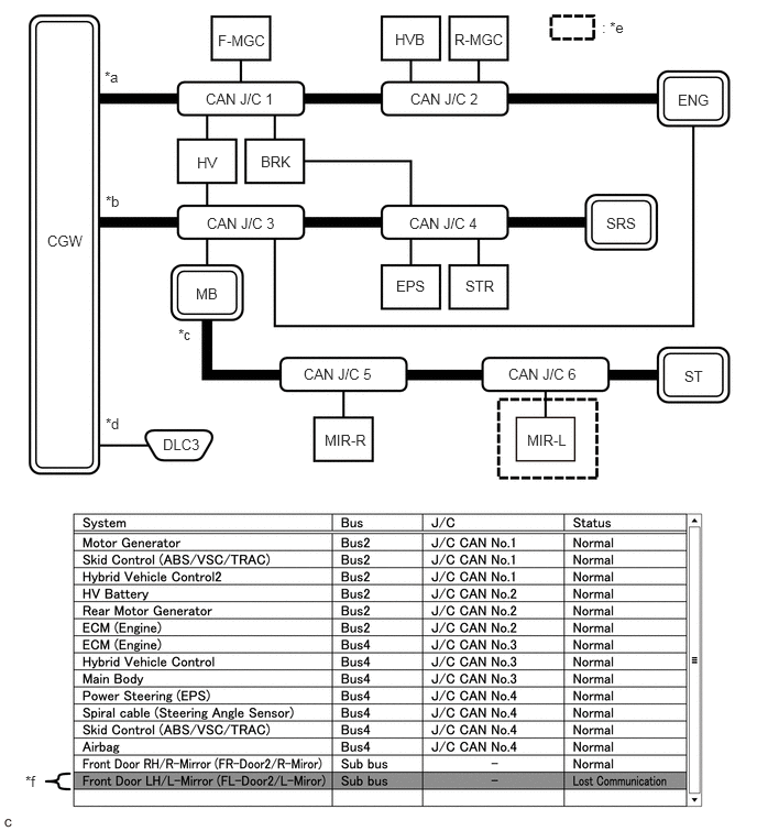
| *a | Bus 2 | *b | Bus 4 |
| *c | Sub bus | *d | Diagnosis bus |
| *e | Location of malfunction | *f | Background color is red |
- HINT:
- ·
The malfunction in the sub bus will not affect the other buses.
·When a gateway function equipped ECU memorizes ECUs and sensors connected to its respective sub bus and there is a communication malfunction in one of the ECUs or sensors, the background color of the ECU or sensor will change to red and the ECU or sensor will remain displayed.
·The information displayed on the "Communication Bus Check" screen will be the same for an open in both wires of a branch line, an internal malfunction of an ECU or sensor or a malfunction in the power supplied to an ECU or sensor.
| Details of Malfunction | Open in both wires of the branch line connected to MIR-L in the sub bus |
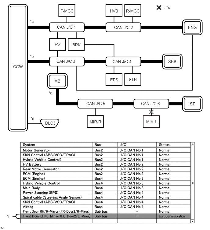
| *a | Bus 2 | *b | Bus 4 |
| *c | Sub bus | *d | Diagnosis bus |
| *e | Location of malfunction | *f | Background color is red |
- HINT:
- ·
The malfunction in the sub bus will not affect the other buses.
·When a gateway function equipped ECU memorizes ECUs and sensors connected to its respective sub bus and there is a communication malfunction in one of the ECUs or sensors, the background color of the ECU or sensor will change to red and the ECU or sensor will remain displayed.
·The information displayed on the "Communication Bus Check" screen will be the same for an open in both wires of a branch line, an internal malfunction of an ECU or sensor or a malfunction in the power supplied to an ECU or sensor.
Problem Symptom Pattern I
| Details of Malfunction | Open in both wires of the main bus line in the sub bus |
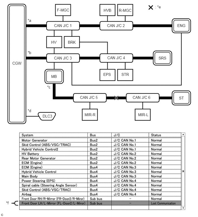
| *a | Bus 2 | *b | Bus 4 |
| *c | Sub bus | *d | Diagnosis bus |
| *e | Location of malfunction | *f | Background color is red |
- HINT:
-
Due to the malfunction, ECUs or sensors farther from the sub bus monitoring ECU (gateway function equipped ECU) than the open in the wires will be displayed as not communicating and their background color will be red.
How to Use "Communication Bus check (Detail)" Screen in Inspection
If the CAN communication system is currently normal but has communication stop history, determine the malfunctioning part using Communication Bus Check (Detail) as follows:
- NOTICE:
- ·
The following CAN bus wiring diagram or communication bus check screen is provided only as an example. This wiring diagram or screen differs from the actual one for this vehicle.
·The Lost Communication Time column displays the longest period of time in seconds that the central gateway ECU (network gateway ECU) detected a communication stop in the respective ECU or sensor.
·The Lost Communication Trip column displays the trip in which the central gateway ECU (network gateway ECU) detected the longest communication stop in the respective ECU or sensor.
·When using the combo box, it may be possible to select a sub bus from the drop down list that does not have any connected ECUs or sensors. This is not a malfunction and occurs when there is no optional device connected to a sub bus which is monitored by a sub bus monitoring ECU (gateway function equipped ECU).
·In the drop down list, all sub buses applicable to the model are displayed (e.g. LIN communication sub buses are also displayed). For information on sub buses necessary to diagnose CAN communication system, refer to the System Diagram.
- HINT:
- ·
If the CAN communication system is currently malfunctioning, it is recommended to use Communication Bus Check rather than Communication Bus Check (Detail) for determining the suspected area.
·The communication error history of ECUs or sensors which have communication error history can be displayed on the "Communication Bus Check (Detail)" screen.
·Lost Communication Time and Lost Communication Trip are only displayed for the central bus.
·Lost Communication Time and Lost Communication Trip are not displayed for sub buses.
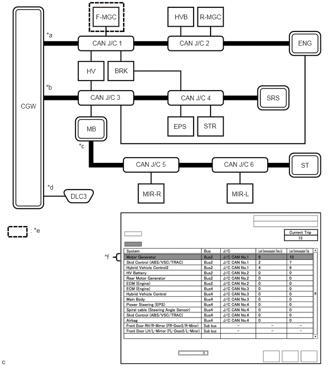
If there is an ECU or sensor displayed with a red background on the "Communication Bus Check (Detail)" screen to indicate that it was not communicating, it is suspected that the ECU or sensor was not communicating.
| Details of Malfunction | Past malfunction in the wire harness or power supplied to F-MGC in Bus 2 |
| *a | Bus 2 | *b | Bus 4 |
| *c | Sub bus | *d | Diagnosis bus |
| *e | Location of malfunction | *f | Background color is red |
| Bus Type | Background Color | Connection Status |
|---|---|---|
| Bus | White | Either of the following:
·
Communication has been normal. ·
Lost Communication Time is below 6 seconds. |
| Red | Lost Communication Time is 6 seconds or more. | |
| Not displayed | Either of the following:
·
The central gateway ECU (network gateway ECU) has an internal malfunction or cannot communicate with the GTS.*1 ·
No ECUs or sensors are connected to the bus.*2 |
|
| Sub bus | White | Lost Communication Time is displayed as "-". |
| Not displayed | Either of the following:
·
The gateway function equipped ECU cannot communicate with the central gateway ECU.*3 ·
No ECUs or sensors are connected to the sub bus.*4 |
- HINT:
- ·
Check the values of Lost Communication Trip and Current Trip for the ECUs or sensors that have a red background color.
·If the values of Lost Communication Trip and Current Trip are the same for an ECU or sensor, the ECU or sensor is currently not communicating. In this case, it is recommended to use Communication Bus Check rather than Communication Bus Check (Detail) for determining the suspected area.
·In the "Communication Bus Check (Detail)" screen shown in the illustration, F-MGC had a communication malfunction in the 10th trip. Thus, it is suspected that F-MGC was not communicating.
·*1: When the central gateway ECU (network gateway ECU) has an internal malfunction or cannot communicate with the GTS, the name of buses, sub buses, ECUs and sensors will not be displayed.
·*2: When no ECUs or sensors are connected to a bus, the message "There is no system found on the communication Bus." will be displayed.
·*3: When a gateway function equipped ECU cannot communicate with the central gateway ECU (network gateway ECU), the name of sub buses and ECUs or sensors connected to the sub bus will not be displayed.
·*4: When no ECUs or sensors are connected to the sub bus, the message "There is no system found on the communication Bus." will be displayed.
CAN BUS WAVEFORMS
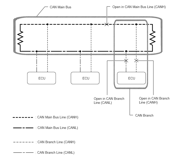
- HINT:
- ·
This waveform is measured between terminals CANH and GND, and terminals CANL and GND of the central gateway ECU (network gateway ECU). (Use this as a reference for diagnosis of CAN communication lines.)
·When malfunctions in multiple ECUs are suspected based on the CAN bus check and DTCs checked using the GTS, check the resistance of the CAN bus using an ohmmeter first. If no problems are found, check the following waveforms.
·If a waveform is not similar to one of the following 3 patterns (Group 1), then an open in a CAN main bus line, an open in a CAN branch line, or a short between a CAN line (CANH or CANL) and ground is suspected (Group 2).
·Wiggle the connector and wire harness to check if the waveform changes.
CAN bus waveforms (Group 1)
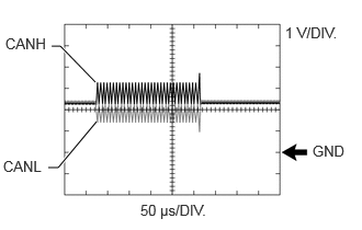
Normal waveform
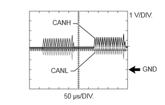
Open in both of the lines (CANH and CANL) of a CAN branch
- HINT:
- ·
Waveforms (waveforms shown using dotted lines) are not output from an ECU or sensor connected to a CAN branch with an open circuit in both lines. (Waveforms from other ECUs or sensors are normal.)
·Because this waveform is similar to a normal waveform, instead of using the waveform, the malfunctioning part can be narrowed down by performing a CAN bus check.
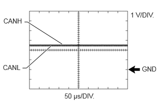
Short between the CAN bus lines (CANH and CANL)
- HINT:
- ·
Waveforms disappear.
·If the malfunction is in an ECU, disconnecting the ECU will change the waveform. If the waveform does not change, a malfunction in the wire harness is suspected.
CAN bus waveforms (reference) (Group 2)
- NOTICE:
-
The following CAN bus waveforms can be used only as reference. the actual measured waveform may differ significantly depending on the location of the open or short circuit.
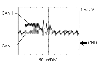
Open in a CAN branch line (CANH)
- HINT:
- ·
An abnormal waveform is output from an ECU with an open in one of its CAN branch lines. Because this abnormal output interferes with the signals from other ECUs, the output of other ECUs will also appear abnormal.
·Narrow down the malfunctioning part by checking DTCs or performing a CAN bus check, or by checking waveform changes when ECUs or sensors are disconnected. the waveform will change to one for an open in both sides of a CAN branch when the ECU or sensor with an open CAN branch line is disconnected.
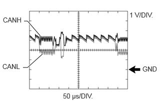
Open in a CAN branch line (CANL)
- HINT:
- ·
An abnormal waveform is output from an ECU with an open in one of its CAN branch lines. Because this abnormal output interferes with the signals from other ECUs, the output of other ECUs will also appear abnormal.
·Narrow down the malfunctioning part by checking DTCs or performing a CAN bus check, or by checking waveform changes when ECUs or sensors are disconnected. the waveform will change to one for an open in both sides of a CAN branch when the ECU or sensor with an open CAN branch line is disconnected.
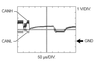
Open in a CAN main bus line (CANH)
- HINT:
- ·
Waveforms of ECUs or sensors that are closer to the central gateway ECU (network gateway ECU) than the open part are almost normal.
·Waveforms of ECUs or sensors that are on the opposite side of the central gateway ECU (network gateway ECU) from the open part are abnormal.
·An open in a CAN main bus line can be confirmed by measuring the resistance between the CANH and CANL terminals of any CAN branch.
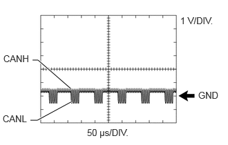
Short between a CAN bus line (CANH) and ground
- HINT:
- ·
Narrow down the shorted part by checking for waveform changes when disconnecting connectors from the CAN junction connectors or when disconnecting ECUs or sensors.
·A short to ground in the CANH line can be confirmed by measuring the resistance between CANH and ground using an ohmmeter.
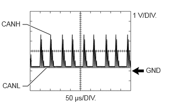
Short between a CAN bus line (CANL) and ground
- HINT:
- ·
Narrow down the shorted part by checking for waveform changes when disconnecting connectors from the CAN junction connectors or when disconnecting ECUs or sensors.
·A short to ground in the CANL line can be confirmed by measuring the resistance between CANL and ground using an ohmmeter.