SUPPLEMENTAL RESTRAINT SYSTEMS CENTER AIRBAG SENSOR ASSEMBLY REMOVAL
CAUTION / NOTICE / HINT
The necessary procedures (adjustment, calibration, initialization or registration) that must be performed after parts are removed, installed or replaced during the airbag ECU assembly removal/installation are shown below.
| Replaced Part or Performed Procedures | Necessary Procedures | Effect/Inoperative Function When Necessary Procedures are not Performed | Link |
|---|---|---|---|
| Airbag ECU assembly | ·
Clear the zero point calibration data and stored linear solenoid valve calibration data ·
Perform initialization and calibration of the linear solenoid valve ·
Perform yaw rate and acceleration sensor zero point calibration |
·
DTCs are stored ·
ABS warning light illuminates ·
Brake warning light / yellow (minor malfunction) illuminates ·
Slip indicator light illuminates ·
Electronically controlled brake system disabled or malfunctions |
( 202304,999999,_54,_083077,_0401811,RM1000000029TH7,) 202304,999999,_54,_083077,_0401811,RM1000000029TH7,)
|
| ECU configuration | - | (202405,999999,_V1,_083041,_0402305,RM100000002M670,)
|
|
| Update ECU security key | Vehicle Control History (RoB) are stored | (202405,999999,_V1,_083041,_0402305,RM100000002ISNL,)
|
|
·
Write the VIN/Vehicle Identification Number ·
Switch the specification information |
- | for GTMC Made:
( 202405,999999,_58,_083100,_0694959,RM100000002LV18,)
for SFTM Made: ( 202409,999999,_58,_083100,_0694957,RM100000002NSNZ,)
|
- HINT:
-
When the cable is disconnected/reconnected to the auxiliary battery terminal, systems temporarily stop operating. However, each system has a function that completes learning the first time the system is used.
- ·
Learning completes when vehicle is driven
Effect/Inoperative Function When Necessary Procedures are not Performed Necessary Procedures Link Lane tracing assist system Drive the vehicle straight ahead at 35 km/h (22 mph) or more for 5 second or more. ( 201910,999999,_58,_083101,_0401880,RM100000001JE9I,)
Pre-collision system
·Learning completes when vehicle is operated normally
Effect/Inoperative Function When Necessary Procedures are not Performed Necessary Procedures Link Power back door function Fully close the back door by hand.
- HINT:
-
Initialization is not necessary if the above procedures are performed while the back door is closed.
( 202304,999999,_59,_083093,_0584672,RM1000000029PGT,)
Power door lock control system If the back door is locked and therefore cannot be opened, it is necessary to unlock the back door using the door control switch, electrical key transmitter sub-assembly switch. ( 202409,999999,_58,_083092,_0403003,RM100000002NS90,)
Air conditioning system After the ignition switch is turned to ON, the servo motor standard position is recognized -
| Replaced Part or Performed Procedures | Necessary Procedures | Effect/Inoperative Function When Necessary Procedures are not Performed | Link |
|---|---|---|---|
| Airbag ECU assembly | ·
Perform reset memory ·
Perform acceleration sensor zero point calibration and store system information memorization |
·
VSC is disabled or malfunctions ·
DTCs are output ·
Slip indicator light illuminates ·
ABS warning light illuminates |
(202304,999999,_54,_083077,_0402316,RM100000002AG8P,)
|
for GF1A:
Reset memory |
Dynamic torque control AWD system | (202409,999999,_52,_083067,_0401881,RM100000002NJ1J,)
|
|
for GF2A:
ECU data initialization |
Dynamic torque vectoring AWD system | (201910,999999,_52,_083068,_0401882,RM100000001JEAV,)
|
|
| ECU configuration | - | (202405,999999,_V1,_083041,_0402305,RM100000002M670,)
|
|
| Update ECU security key | Vehicle Control History (RoB) are stored | (202405,999999,_V1,_083041,_0402305,RM100000002ISNL,)
|
|
·
Write the VIN/Vehicle Identification Number ·
Switch the specification information |
- | for GTMC Made:
( 202405,999999,_58,_083100,_0694959,RM100000002LV18,)
for SFTM Made: ( 202409,999999,_58,_083100,_0694957,RM100000002NSNZ,)
|
- HINT:
-
When the cable is disconnected/reconnected to the auxiliary battery terminal, systems temporarily stop operating. However, each system has a function that completes learning the first time the system is used.
- ·
Learning completes when vehicle is driven
Effect/Inoperative Function When Necessary Procedures are not Performed Necessary Procedures Link Stop and start system Drive the vehicle until stop and start control is permitted (approximately 5 to 60 minutes). ( 202409,999999,_51,_083056,_0402418,RM100000002NSFO,)
Lane tracing assist system Drive the vehicle straight ahead at 15 km/h (10 mph) or more for 1 second or more. ( 201910,999999,_58,_083101,_0401880,RM100000001JE9I,)
Pre-collision system
·Learning completes when vehicle is operated normally
Effect/Inoperative Function When Necessary Procedures are not Performed Necessary Procedures Link *: w/ Power back door system
Power back door function* Fully close the back door by hand.
- HINT:
-
Initialization is not necessary if the above procedures are performed while the back door is closed.
( 202304,999999,_59,_083093,_0584672,RM1000000029PGT,)
Power door lock control system If the back door is locked and therefore cannot be opened, it is necessary to unlock the back door using the door control switch, electrical key transmitter sub-assembly switch. ( 202409,999999,_58,_083092,_0403003,RM100000002NS90,)
Air conditioning system After the ignition switch is turned to ON, the servo motor standard position is recognized -
PROCEDURE

 1. PRECAUTION
- CAUTION:
-
-
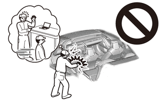
Be sure to read Precaution thoroughly before servicing.
- ·
- NOTICE:
-
After turning the ignition switch off, waiting time may be required before disconnecting the cable from the auxiliary negative (-) battery terminal.
2.DISCONNECT CABLE FROM NEGATIVE AUXILIARY BATTERY TERMINAL
- CAUTION:
-
- ·
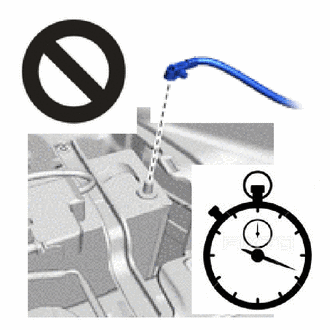
Wait at least 60 seconds after disconnecting the cable from the negative (-) auxiliary battery terminal to disable the SRS system.
·If the airbag deploys for any reason, it may cause a serious accident.
for M20C-FKS:
Click hereGeneral>MAINTENANCE>M20C-FKS BATTERY>REMOVAL202409,999999,_V1,_083136,_0418197,RM100000002NHPI,
for M20D-FKS:
Click hereGeneral>MAINTENANCE>M20D-FKS BATTERY>REMOVAL202409,999999,_V1,_083136,_0403617,RM100000002NHPJ,
58810J
3.REMOVE CONSOLE BOX ASSEMBLY
58861B
4.REMOVE NO. 1 CONSOLE BOX DUCT
89170A
5.REMOVE AIRBAG ECU ASSEMBLY
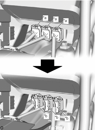
| *a | Push the Connector Lock |
| *b | Pull Out the Lock Lever |
Pull out each connector with its connector lock pushed to disconnect the 3 connectors.
- NOTICE:
-
When disconnecting any airbag connector, take care not to damage the airbag wire harness.
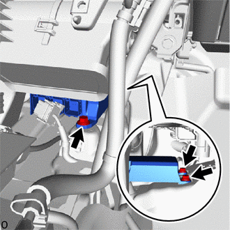
Remove the 3 bolts and airbag ECU assembly.
- NOTICE:
-
If the airbag ECU assembly has been dropped, or there are any cracks, dents or other defects in the case or connector, replace the airbag ECU assembly with a new one.