METER / GAUGE / DISPLAY COMBINATION METER REMOVAL
CAUTION / NOTICE / HINT
The necessary procedures (adjustment, calibration, initialization, or registration) that must be performed after parts are removed and installed, or replaced during combination meter assembly removal/installation are shown below.
| Replaced Part or Performed Procedure | Necessary Procedure | Effect/Inoperative Function When Necessary Procedures are not Performed | Link |
|---|---|---|---|
| Combination meter assembly | Update ECU security key | Vehicle control history (RoB) are stored | ( 202405,999999,_V1,_083041,_0402305,RM100000002ISNL,) 202405,999999,_V1,_083041,_0402305,RM100000002ISNL,)
|
- NOTICE:
-
When replacing the combination meter assembly, always replace it with a new one. If a combination meter assembly which was installed to another vehicle is used, the information stored in it will not match the information from the vehicle and a DTC may be stored.
PROCEDURE

 55474B
1.REMOVE INSTRUMENT CLUSTER FINISH PANEL GARNISH
55474B
1.REMOVE INSTRUMENT CLUSTER FINISH PANEL GARNISH
55410C
2.REMOVE INSTRUMENT CLUSTER FINISH PANEL ASSEMBLY
83100
3.REMOVE COMBINATION METER ASSEMBLY
except 12.3 Inch Display:
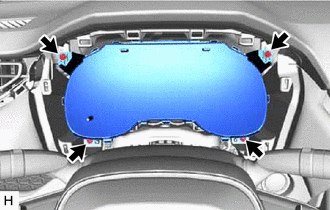
Remove the 4 screws.
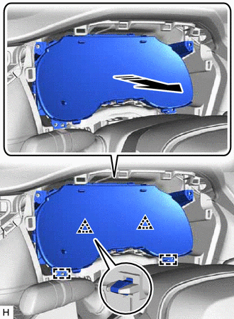

|
Remove in this Direction |
Pull towards the rear of the vehicle to detach the clip and guide and remove the combination meter assembly.
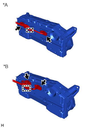
| *A | for 4.2 Inch Display |
| *B | for 7 Inch Display |
Detach the clamp and disconnect the 2 connectors.
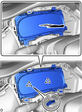
for 12.3 Inch Display:
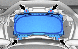
Remove the 4 screws.
|
|
Remove in this Direction |
Pull towards the rear of the vehicle to detach the clip and guide and remove the combination meter assembly.
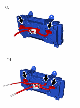
| *A | for Radio and Display Receiver Type |
| *B | for Radio and Navigation Receiver Type |
Detach the clamp and disconnect the each connector.