RM36D0EC _51 Engine / Hybrid System _083056 STOP AND START _0402418 STOP AND START SYSTEM J

STOP AND START  STOP AND START SYSTEM  Starter Signal Circuit  


DESCRIPTION

The engine stop and start ECU can activate the ST NO. 1 relay to operate the starter assembly.

WIRING DIAGRAM
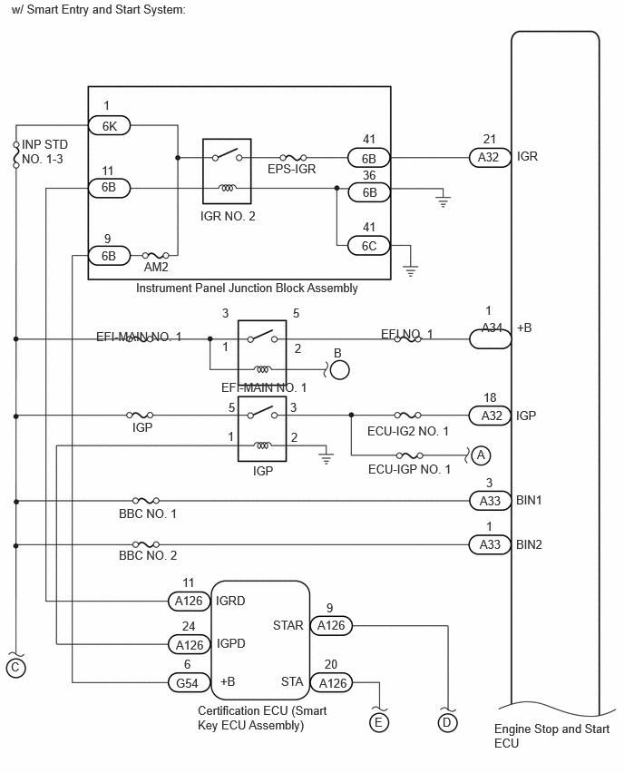
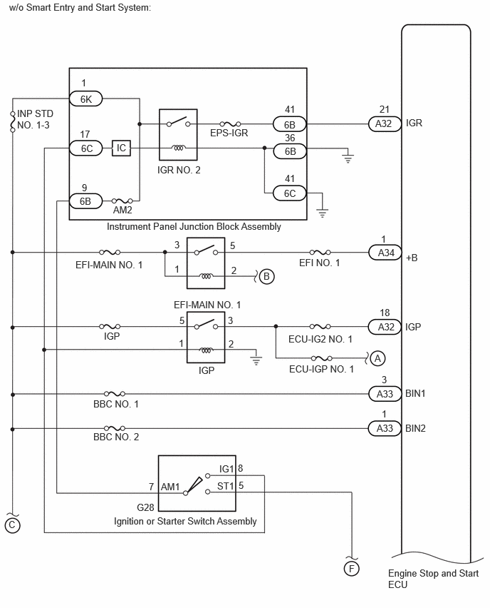
A570166E01
0.25,1.573 0.802,2.104 0.552,0.531 10 false INP STD NO. 1-3 1.656,2.979 2.115,3.177 0.458,0.198 10 false AM2 1.563,3.219 4.771,3.5 3.208,0.281 10 false Instrument Panel Junction Block Assembly 2.302,2.396 3.073,2.615 0.771,0.219 10 false IGR NO. 2 3.073,1.854 3.906,2.073 0.833,0.219 10 false EPS-IGR 1.104,3.781 2.26,4.042 1.156,0.26 10 false EFI-MAIN NO. 1 4.375,3.75 5.531,4.01 1.156,0.26 10 false EFI NO. 1 2.542,4.365 3.698,4.625 1.156,0.26 10 false EFI-MAIN NO. 1 2.906,5.323 4.063,5.583 1.156,0.26 10 false IGP 5.49,1.719 6.323,1.938 0.833,0.219 10 false A32 5.531,3.677 6.365,3.896 0.833,0.219 10 false A34 2.271,8.073 3.792,8.594 1.521,0.521 10 false Certification ECU (Smart Key ECU Assembly) 5.677,8.281 7.063,8.688 1.385,0.406 10 false Engine Stop and Start ECU 5.479,5.135 6.635,5.396 1.156,0.26 10 false A 3.833,3.969 4.99,4.229 1.156,0.26 10 false B 2.021,7.76 3.177,8.021 1.156,0.26 10 false G54 2.49,7.302 3.646,7.563 1.156,0.26 10 false IGPD 2.531,7.74 3.688,8 1.156,0.26 10 false +B 3.135,7.094 4.292,7.354 1.156,0.26 10 false STAR 3.229,7.74 4.385,8 1.156,0.26 10 false STA 3.646,7.094 4.802,7.354 1.156,0.26 10 false A126 3.667,7.76 4.823,8.021 1.156,0.26 10 false A126 2.094,6.604 3.25,6.865 1.156,0.26 10 false 11 2.115,7.542 3.271,7.802 1.156,0.26 10 false 6 3.75,6.896 4.906,7.156 1.156,0.26 10 false 9 3.729,7.542 4.885,7.802 1.156,0.26 10 false 20 5.083,8.208 6.24,8.469 1.156,0.26 10 false D 0.125,7.573 1.281,7.833 1.156,0.26 10 false C 4.302,8.208 5.458,8.469 1.156,0.26 10 false E 5.927,4.688 6.76,4.906 0.833,0.219 10 false IGP 5.938,1.708 6.771,1.927 0.833,0.219 10 false IGR 5.938,3.677 6.771,3.896 0.833,0.219 10 false +B 5.573,3.479 6.406,3.698 0.833,0.219 10 false 1 5.552,4.479 6.385,4.698 0.833,0.219 10 false 18 1.177,1.365 1.635,1.563 0.458,0.198 10 false 6K 1.167,2.063 1.625,2.26 0.458,0.198 10 false 6B 1.167,2.854 1.625,3.052 0.458,0.198 10 false 6B 4.156,2.74 4.615,2.938 0.458,0.198 10 false 6C 1.188,1.125 1.646,1.323 0.458,0.198 10 false 1 1.167,1.875 1.625,2.073 0.458,0.198 10 false 11 1.198,2.656 1.656,2.854 0.458,0.198 10 false 9 4.167,1.51 4.625,1.708 0.458,0.198 10 false 41 4.167,2.521 4.625,2.719 0.458,0.198 10 false 41 2.552,3.51 3.01,3.708 0.458,0.198 10 false 3 3.333,4.594 3.792,4.792 0.458,0.198 10 false 3 2.552,3.896 3.01,4.094 0.458,0.198 10 false 1 3.365,3.51 3.823,3.708 0.458,0.198 10 false 5 3.385,3.917 3.844,4.115 0.458,0.198 10 false 2 3.344,4.938 3.802,5.135 0.458,0.198 10 false 2 2.615,4.927 3.073,5.125 0.458,0.198 10 false 1 2.625,4.594 3.083,4.792 0.458,0.198 10 false 5 4.229,5.302 5.385,5.563 1.156,0.26 10 false ECU-IGP NO. 1 5.552,1.51 6.385,1.729 0.833,0.219 10 false 21 5.51,5.667 5.969,5.865 0.458,0.198 10 false A33 5.51,6.167 5.969,6.365 0.458,0.198 10 false A33 5.927,5.656 6.542,5.854 0.615,0.198 10 false BIN1 5.927,6.167 6.542,6.365 0.615,0.198 10 false BIN2 5.583,5.458 5.74,5.656 0.156,0.198 10 false 3 5.583,5.958 5.74,6.156 0.156,0.198 10 false 1 1.365,6.292 2.594,6.49 1.229,0.198 10 false BBC NO. 2 1.365,5.813 2.594,6.01 1.229,0.198 10 false BBC NO. 1 0.135,0.021 5.031,0.219 4.896,0.198 10 false w/ Smart Entry and Start System: 5.531,4.688 6.365,4.906 0.833,0.219 10 false A32 4.219,4.865 5.375,5.125 1.156,0.26 10 false ECU-IG2 NO. 1 1.521,4.823 2.677,5.083 1.156,0.26 10 false IGP 2.01,6.813 3.167,7.073 1.156,0.26 10 false A126 2.021,7.323 3.177,7.583 1.156,0.26 10 false A126 2.479,6.813 3.635,7.073 1.156,0.26 10 false IGRD 2.094,7.104 3.25,7.365 1.156,0.26 10 false 24 4.156,1.74 4.615,1.938 0.458,0.198 10 false 6B 4.167,2.125 4.625,2.323 0.458,0.198 10 false 6B 4.167,1.927 4.625,2.125 0.458,0.198 10 false 36

A570167E02
0.25,1.573 0.802,2.104 0.552,0.531 10 false INP STD NO. 1-3 1.656,2.979 2.115,3.177 0.458,0.198 10 false AM2 1.563,3.219 4.771,3.5 3.208,0.281 10 false Instrument Panel Junction Block Assembly 2.302,2.396 3.073,2.615 0.771,0.219 10 false IGR NO. 2 3.073,1.854 3.906,2.073 0.833,0.219 10 false EPS-IGR 1.104,3.781 2.26,4.042 1.156,0.26 10 false EFI-MAIN NO. 1 4.375,3.75 5.531,4.01 1.156,0.26 10 false EFI NO. 1 2.542,4.365 3.698,4.625 1.156,0.26 10 false EFI-MAIN NO. 1 2.906,5.323 4.063,5.583 1.156,0.26 10 false IGP 5.49,1.719 6.323,1.938 0.833,0.219 10 false A32 5.531,3.604 6.365,3.823 0.833,0.219 10 false A34 1.667,7.521 4.302,7.958 2.635,0.438 10 false Ignition or Starter Switch Assembly 5.677,8.281 7.063,8.688 1.385,0.406 10 false Engine Stop and Start ECU 5.479,5.146 6.635,5.406 1.156,0.26 10 false A 3.854,3.948 5.01,4.208 1.156,0.26 10 false B 3.208,6.76 4.365,7.021 1.156,0.26 10 false IG1 3.177,7.01 4.333,7.271 1.156,0.26 10 false ST1 3.479,6.75 4.635,7.01 1.156,0.26 10 false 8 3.49,7 4.646,7.26 1.156,0.26 10 false 5 5.104,8.219 6.26,8.479 1.156,0.26 10 false F 0.125,7.573 1.281,7.833 1.156,0.26 10 false C 5.927,4.688 6.76,4.906 0.833,0.219 10 false IGP 5.938,1.708 6.771,1.927 0.833,0.219 10 false IGR 5.938,3.677 6.771,3.896 0.833,0.219 10 false +B 5.573,3.406 6.406,3.625 0.833,0.219 10 false 1 5.552,4.479 6.385,4.698 0.833,0.219 10 false 18 1.177,1.365 1.635,1.563 0.458,0.198 10 false 6K 1.167,2.854 1.625,3.052 0.458,0.198 10 false 6B 4.156,2.74 4.615,2.938 0.458,0.198 10 false 6C 1.188,1.125 1.646,1.323 0.458,0.198 10 false 1 1.167,1.875 1.625,2.073 0.458,0.198 10 false 17 1.198,2.656 1.656,2.854 0.458,0.198 10 false 9 4.167,1.51 4.625,1.708 0.458,0.198 10 false 41 4.167,2.521 4.625,2.719 0.458,0.198 10 false 41 2.552,3.49 3.01,3.688 0.458,0.198 10 false 3 3.333,4.594 3.792,4.792 0.458,0.198 10 false 3 2.552,3.844 3.01,4.042 0.458,0.198 10 false 1 3.365,3.5 3.823,3.698 0.458,0.198 10 false 5 3.385,3.865 3.844,4.063 0.458,0.198 10 false 2 3.344,4.938 3.802,5.135 0.458,0.198 10 false 2 2.615,4.927 3.073,5.125 0.458,0.198 10 false 1 2.625,4.594 3.083,4.792 0.458,0.198 10 false 5 4.229,5.302 5.385,5.563 1.156,0.26 10 false ECU-IGP NO. 1 5.552,1.51 6.385,1.729 0.833,0.219 10 false 21 5.51,5.667 5.969,5.865 0.458,0.198 10 false A33 5.51,6.167 5.969,6.365 0.458,0.198 10 false A33 5.927,5.656 6.542,5.854 0.615,0.198 10 false BIN1 5.927,6.167 6.542,6.365 0.615,0.198 10 false BIN2 5.583,5.458 5.74,5.656 0.156,0.198 10 false 3 5.583,5.958 5.74,6.156 0.156,0.198 10 false 1 1.365,6.292 2.594,6.49 1.229,0.198 10 false BBC NO. 2 1.365,5.813 2.594,6.01 1.229,0.198 10 false BBC NO. 1 0.135,0.021 5.031,0.219 4.896,0.198 10 false w/o Smart Entry and Start System: 5.531,4.688 6.365,4.906 0.833,0.219 10 false A32 4.219,4.865 5.375,5.125 1.156,0.26 10 false ECU-IG2 NO. 1 1.521,4.823 2.677,5.083 1.156,0.26 10 false IGP 2,7.323 3.156,7.583 1.156,0.26 10 false G28 2.177,7.021 3.333,7.281 1.156,0.26 10 false 7 4.156,1.74 4.615,1.938 0.458,0.198 10 false 6B 4.167,2.125 4.625,2.323 0.458,0.198 10 false 6B 4.167,1.927 4.625,2.125 0.458,0.198 10 false 36 2.354,7.021 2.813,7.219 0.458,0.198 10 false AM1 1.188,2.083 1.646,2.281 0.458,0.198 10 false 6C 1.708,2.073 2.167,2.271 0.458,0.198 10 false IC

A574948E01
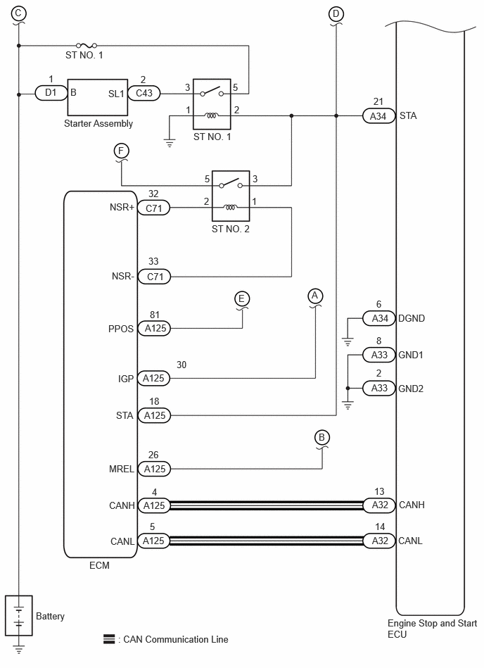
0.219,0.104 1.146,0.313 0.927,0.208 10 false C 1.75,2.146 2.677,2.354 0.927,0.208 10 false F 4.927,0.115 5.854,0.323 0.927,0.208 10 false D 3.531,4.333 4.458,4.542 0.927,0.208 10 false E 4.615,4.281 5.542,4.49 0.927,0.208 10 false A 4.719,6.385 5.646,6.594 0.927,0.208 10 false B 1.719,6.063 2.646,6.271 0.927,0.208 10 false STA 5.917,1.625 6.844,1.833 0.927,0.208 10 false STA 1.042,1.281 1.969,1.49 0.927,0.208 10 false B 0.667,1.281 1.594,1.49 0.927,0.208 10 false D1 0.719,1.083 1.646,1.292 0.927,0.208 10 false 1 2.01,1.292 2.938,1.5 0.927,0.208 10 false C43 1.604,1.302 2.531,1.51 0.927,0.208 10 false SL1 2.083,1.094 3.01,1.302 0.927,0.208 10 false 2 1.75,9.375 4.667,9.604 2.917,0.229 10 false : CAN Communication Line 5.896,4.625 6.823,4.833 0.927,0.208 10 false DGND 5.896,5.167 6.823,5.375 0.927,0.208 10 false GND1 5.896,5.667 6.823,5.875 0.927,0.208 10 false GND2 5.906,7.385 6.833,7.594 0.927,0.208 10 false CANH 1.615,7.396 2.542,7.604 0.927,0.208 10 false CANH 1.635,7.927 2.563,8.135 0.927,0.208 10 false CANL 5.896,7.917 6.823,8.125 0.927,0.208 10 false CANL 1.323,8.281 2.25,8.49 0.927,0.208 10 false ECM 5.479,1.635 6.406,1.844 0.927,0.208 10 false A34 5.51,4.625 6.438,4.833 0.927,0.208 10 false A34 5.5,5.167 6.427,5.375 0.927,0.208 10 false A33 5.5,5.656 6.427,5.865 0.927,0.208 10 false A33 5.51,7.385 6.438,7.594 0.927,0.208 10 false A32 5.51,7.917 6.438,8.125 0.927,0.208 10 false A32 5.531,1.417 6.458,1.625 0.927,0.208 10 false 21 5.573,5.438 6.5,5.646 0.927,0.208 10 false 2 5.573,4.417 6.5,4.625 0.927,0.208 10 false 6 5.573,4.958 6.5,5.167 0.927,0.208 10 false 8 5.542,7.188 6.469,7.396 0.927,0.208 10 false 13 5.552,7.708 6.479,7.917 0.927,0.208 10 false 14 5.74,9.135 7.156,9.542 1.417,0.406 10 false Engine Stop and Start ECU 0.531,9.031 1.458,9.24 0.927,0.208 10 false Battery 2.865,1.938 3.792,2.146 0.927,0.208 10 false ST NO. 1 3.135,3.302 4.063,3.51 0.927,0.208 10 false ST NO. 2 2.156,3 3.083,3.208 0.927,0.208 10 false C71 2.177,4.01 3.104,4.219 0.927,0.208 10 false C71 1.625,2.979 2.552,3.188 0.927,0.208 10 false NSR+ 1.656,4 2.583,4.208 0.927,0.208 10 false NSR- 3.021,2.896 3.948,3.104 0.927,0.208 10 false 2 3.729,2.896 4.656,3.104 0.927,0.208 10 false 1 2.75,1.542 3.677,1.75 0.927,0.208 10 false 1 3.469,1.542 4.396,1.75 0.927,0.208 10 false 2 3.74,2.563 4.667,2.771 0.927,0.208 10 false 3 3.031,2.563 3.958,2.771 0.927,0.208 10 false 5 3.448,1.208 4.375,1.417 0.927,0.208 10 false 5 2.74,1.208 3.667,1.417 0.927,0.208 10 false 3 0.969,0.729 1.896,0.938 0.927,0.208 10 false ST NO. 1 0.948,1.74 2.833,2.01 1.885,0.271 10 false Starter Assembly 2.198,2.781 3.125,2.99 0.927,0.208 10 false 32 2.198,3.781 3.125,3.99 0.927,0.208 10 false 33 1.604,4.781 2.531,4.99 0.927,0.208 10 false PPOS 2.146,4.771 3.073,4.979 0.927,0.208 10 false A125 2.115,5.51 3.042,5.719 0.927,0.208 10 false A125 2.135,6.063 3.063,6.271 0.927,0.208 10 false A125 2.135,6.854 3.063,7.063 0.927,0.208 10 false A125 2.125,7.396 3.052,7.604 0.927,0.208 10 false A125 2.115,7.917 3.042,8.125 0.927,0.208 10 false A125 1.75,5.521 2.677,5.729 0.927,0.208 10 false IGP 1.615,6.854 2.542,7.063 0.927,0.208 10 false MREL 2.219,7.708 3.146,7.917 0.927,0.208 10 false 5 2.25,7.198 3.177,7.406 0.927,0.208 10 false 4 2.219,4.573 3.146,4.781 0.927,0.208 10 false 81 2.208,5.854 3.135,6.063 0.927,0.208 10 false 18 2.615,5.313 3.542,5.521 0.927,0.208 10 false 30 2.198,6.646 3.125,6.854 0.927,0.208 10 false 26

Refer to Neutral Position Switch Circuit.

Click hereEngine / Hybrid System>STOP AND START>STOP AND START SYSTEM>Neutral Position Switch Circuit

CAUTION / NOTICE / HINT

NOTICE:
·

Before replacing the engine stop and start ECU, read the number of starter operations and write it into a new engine stop and start ECU.

Click hereEngine / Hybrid System>STOP AND START>STOP AND START SYSTEM>REGISTRATION

·

After replacing the engine stop and start ECU or air conditioning amplifier assembly, reset and perform learning of the air conditioning information in the engine stop and start ECU.

Click hereEngine / Hybrid System>STOP AND START>STOP AND START SYSTEM>REGISTRATION

·

After replacing the engine stop and start ECU or airbag ECU assembly, clear and calibrate the deceleration sensor zero point in the engine stop and start ECU.

Click hereEngine / Hybrid System>STOP AND START>STOP AND START SYSTEM>REGISTRATION

·

Bleed the oil pump with motor assembly (continuously variable transaxle assembly) after removing and installing the continuously variable transaxle assembly or replacing the CVT fluid.

Click hereEngine / Hybrid System>STOP AND START>STOP AND START SYSTEM>HOW TO PROCEED WITH TROUBLESHOOTING

·

After replacing the starter assembly, perform initialization of the number of starter operations stored in the engine stop and start ECU.

Click hereEngine / Hybrid System>STOP AND START>STOP AND START SYSTEM>REGISTRATION

·

When the starter assembly is replaced, "ST NO. 1 relay" must be also replaced.

·

Inspect the fuses for circuits related to this system before performing the following procedure.

·

After the ignition switch is turned off, there may be a waiting time before disconnecting the negative (-) battery terminal.

Click hereGeneral>SETUP>WHEN DISCONNECTING OR RECONNECTING BATTERY TERMINAL>BEFORE DISCONNECTING BATTERY

·

When disconnecting and reconnecting the battery.

HINT:

When disconnecting and reconnecting the battery, there is an automatic learning function that completes learning when the respective system is used.

Click hereGeneral>SETUP>WHEN DISCONNECTING OR RECONNECTING BATTERY TERMINAL>AUTOMATIC LEARNING CHART


PROCEDURE

1.CHECK CRANKING
a.

Turn the ignition switch START and check that the engine cranks.


Result:
Result Proceed to
Engine cranks A
Engine does not crank B


A

2.PERFORM ACTIVE TEST USING GTS (STARTER(HOOD CLOSE))

B

19.PERFORM ACTIVE TEST USING GTS (STARTER(HOOD CLOSE))
2.PERFORM ACTIVE TEST USING GTS (STARTER(HOOD CLOSE))
a.

Check that the engine hood is closed.


b.

Connect the GTS to the DLC3.


c.

Turn the ignition switch to ON.


d.

Turn the GTS on.


e.

Enter the following menus: Powertrain / Stop and Start / Active Test / Starter(Hood Close).

Powertrain > Stop and Start > Active Test
Tester Display
Starter(Hood Close)
50004 392 42017

f.

Check whether the engine cranks while the Active Test "Starter(Hood Close)" is being performed.

NOTICE:

The Active Test "Starter(Hood Close)" is stopped automatically 3 seconds after the starter assembly begins operating.


Standard:

Engine cranks


Result:
Proceed to
OK
NG


OK

3.CHECK VEHICLE CONTROL HISTORY (ENGINE CONTROL SYSTEM)

NG

14.CHECK HARNESS AND CONNECTOR (BIN1 AND BIN2 TERMINALS POWER SOURCE CIRCUIT)
3.CHECK VEHICLE CONTROL HISTORY (ENGINE CONTROL SYSTEM)
a.

Enter the following menus: Powertrain / Engine / Utility / Vehicle Control History (RoB).

Powertrain > Engine > Utility
Tester Display
Vehicle Control History (RoB)
50005 372 55

b.

Check the vehicle control history (RoB).

Result:
Result Proceed to
Engine control system Vehicle Control History (RoB) is not output A
Engine Difficult to Start is output B
Result other than Engine Difficult to Start is output C


HINT:
·

If the value of "Cranking Time" is approximately 1.5 seconds, the stop and start control system or starter system may be malfunctioning.

·

If the value of "Cranking Time" is small (approximately 0.5 seconds or less: the minimum value varies depending on the model), the engine control system may be malfunctioning.

·

The Data List item "Cranking Time" indicates the length of time starter operation is requested by the engine stop and start ECU. If the engine speed exceeds the specified value, the engine stop and start ECU cancels its start request.


A

5.CHECK VEHICLE CONTROL HISTORY

B

4.CHECK VEHICLE CONTROL HISTORY (ENGINE CONTROL SYSTEM)

C

4.CHECK VEHICLE CONTROL HISTORY (ENGINE CONTROL SYSTEM)
a.

Enter the following menus: Powertrain / Engine / Utility / Vehicle Control History (RoB).

Powertrain > Engine > Utility
Tester Display
Vehicle Control History (RoB)
50005 372 55

b.

Select Engine Difficult to Start from the Vehicle Control History to display the data from the time of control.


c.

Check the output data.

HINT:
·

Checking the freeze frame data allows the vehicle conditions at the time of detection to be confirmed.

·

As Vehicle Control History may be overwritten whenever the trigger conditions are met, make sure to save the Vehicle Control History data before performing any inspections.


Result:
Result Proceed to
Engine speed does not rise to approximately 300 rpm (Starter does not rotate) A
Engine speed rises to approximately 300 rpm (Starter rotates) B


A

5.CHECK VEHICLE CONTROL HISTORY

B

5.CHECK VEHICLE CONTROL HISTORY
a.

Enter the following menus: Powertrain / Stop and Start / Utility / Vehicle Control History (RoB).

Powertrain > Stop and Start > Utility
Tester Display
Vehicle Control History (RoB)
50005 392 55

b.

Select a vehicle control history item to display the data from the time of control.


c.

Check the output data.

Result:
Tester Display Result Proceed to
Engine Stall History during Stop&Start (Collision or Battery Voltage Low) Yes A
Engine Stall History during Engine Starting (Collision) Yes
Engine Start Fail Yes B
Vehicle control history item is not output or No is displayed for the results of all of the freeze frame data above


A

6.CHECK VEHICLE CONDITION (COLLISION HISTORY)

B

7.CHECK HARNESS AND CONNECTOR (ENGINE STOP AND START ECU - ST NO. 1 RELAY)
6.CHECK VEHICLE CONDITION (COLLISION HISTORY)
a.

Check if the vehicle was in a collision when the engine stalled.

Result:
Result Proceed to
Vehicle was in collision when engine stalled A
Vehicle was not in collision when engine stalled B


HINT:

When "Engine Stall History during Stop&Start (Collision or Battery Voltage Low)" or "Engine Stall History during Engine Starting (Collision)" is stored:

This may have been stored because the vehicle was in a collision or a collision detection signal was input while stop and start control was operating.


A

END (ENGINE STALLED BECAUSE COLLISION DETECTION SIGNAL WAS RECEIVED)

B

7.CHECK HARNESS AND CONNECTOR (ENGINE STOP AND START ECU - ST NO. 1 RELAY)
a.

Disconnect the engine stop and start ECU connector.


b.

Remove the ST NO. 1 relay from the NO. 1 engine room relay block and junction block assembly.


c.

Disconnect the certification ECU (smart key ECU assembly) connector.


d.

Disconnect the park/neutral position switch assembly connector.


e.

Disconnect the ECM connector.


f.

Measure the resistance according to the value(s) in the table below.

Standard Resistance:
Tester Connection Condition Specified Condition
A34-21 (STA) - ST NO. 1 relay terminal 2 Always Below 1 Ω
A34-21 (STA) - Body ground Always 10 kΩ or higher
ST NO. 1 relay terminal 2 - Body ground Always 10 kΩ or higher


Result:
Proceed to
OK
NG


OK

8.CHECK HARNESS AND CONNECTOR (ST NO. 1 RELAY - BODY GROUND)

NG

REPAIR OR REPLACE HARNESS OR CONNECTOR

8.CHECK HARNESS AND CONNECTOR (ST NO. 1 RELAY - BODY GROUND)
a.

Remove the ST NO. 1 relay from the NO. 1 engine room relay block and junction block assembly
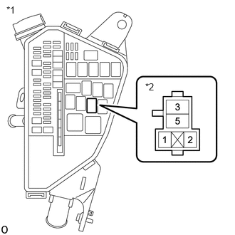

b.

Measure the resistance according to the value(s) in the table below.

Standard Resistance:
Tester Connection Condition Specified Condition
ST NO. 1 relay terminal 1 - Body ground Always Below 1 Ω


Result:
Proceed to
OK
NG


OK

9.CHECK HARNESS AND CONNECTOR (ST NO. 1 RELAY - BATTERY)

NG

REPAIR OR REPLACE HARNESS OR CONNECTOR

9.CHECK HARNESS AND CONNECTOR (ST NO. 1 RELAY - BATTERY)
a.

Remove the ST NO. 1 relays from the NO. 1 engine room relay block and junction block assembly


b.
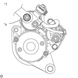
A435792C01
0.094,0.063 0.406,0.219 0.313,0.156 10 false *1 2.125,1.188 2.438,1.344 0.313,0.156 10 false *2
*1 NO. 1 Engine Room Relay Block and Junction Block Assembly
*2 ST NO. 1 Relay Terminal


Measure the voltage according to the value(s) in the table below.

Standard Voltage:
Tester Connection Condition Specified Condition
ST NO. 1 relay terminal 5 - Body ground Always 9.5 to 14 V


Result:
Proceed to
OK
NG


OK

10.CHECK HARNESS AND CONNECTOR (STARTER ASSEMBLY - BATTERY)

NG

REPAIR OR REPLACE HARNESS OR CONNECTOR

10.CHECK HARNESS AND CONNECTOR (STARTER ASSEMBLY - BATTERY)
a.
A434147C01
1.167,0.771 0.542,1.021 0.542,1.021 0.406,1.031 true 0.188,0.104 0.417,0.365 0.229,0.26 10 false *1 0.167,0.99 0.396,1.25 0.229,0.26 10 false *a
*1 Starter Assembly
*a D1-1 (B)


Measure the voltage according to the value(s) in the table below.

Standard Voltage:
Tester Connection Condition Specified Condition
D1-1 (B) - Body ground Always 9.5 to 14 V


NOTICE:

Before performing this step, check that the starter assembly connector C56 is not disconnected or loose.


Result:
Proceed to
OK
NG


OK

11.CHECK HARNESS AND CONNECTOR (ST NO. 1 RELAY - STARTER ASSEMBLY)

NG

REPAIR OR REPLACE HARNESS OR CONNECTOR

11.CHECK HARNESS AND CONNECTOR (ST NO. 1 RELAY - STARTER ASSEMBLY)
a.

Remove the ST NO. 1 relays from the NO. 1 engine room relay block and junction block assembly.


b.

Disconnect the starter assembly connector.


c.

Measure the resistance according to the value(s) in the table below.

Standard Resistance:
Tester Connection Condition Specified Condition
ST NO. 1 relay terminal 3 - C43-2 (SL1) Always Below 1 Ω


Result:
Proceed to
OK
NG


OK

12.INSPECT RELAY (ST NO. 1 RELAY)

NG

REPAIR OR REPLACE HARNESS OR CONNECTOR

12.INSPECT RELAY (ST NO. 1 RELAY)

OK

13.INSPECT STARTER ASSEMBLY

NG

REPLACE RELAY (ST NO. 1 RELAY)

13.INSPECT STARTER ASSEMBLY

OK

REPLACE ENGINE STOP AND START ECU

Click hereEngine / Hybrid System>STOP AND START>ENGINE STOP AND START ECU>REMOVAL

HINT:

If arriving at this item from the item "Drive command is being sent from the engine stop and start ECU but the starter itself is not moving" of "After Engine Stops due to Stop and Start System, Engine does not Restart" in Stop and Start / Stop and Start System / Problem Symptoms Table, go to SIMULATION METHOD.


NG
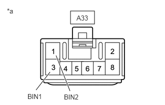
14.CHECK HARNESS AND CONNECTOR (BIN1 AND BIN2 TERMINALS POWER SOURCE CIRCUIT)
A346333C68
1.469,0.229 1.969,0.5 0.5,0.271 1.042,1.5 0.75,1.875 true 1.458,1.896 1.167,1.156 true 1.594,0.292 2.052,0.49 0.458,0.198 10 false A33 0.146,0.146 0.458,0.344 0.313,0.198 10 false *a 0.573,1.927 1,2.146 0.427,0.219 10 false BIN1 1.333,1.938 1.76,2.156 0.427,0.219 10 false BIN2
*a Front view of wire harness connector
(to Engine Stop and Start ECU)


a.

Disconnect the engine stop and start ECU connector.


b.

Measure the voltage according to the value(s) in the table below.

Standard Voltage:
Tester Connection Condition Specified Condition
A33-1 (BIN2) - Body ground Always 9.5 to 14 V
A33-3 (BIN1) - Body ground Always 9.5 to 14 V


Result:
Proceed to
OK
NG


OK

15.CHECK HARNESS AND CONNECTOR (IGR TERMINAL POWER SOURCE CIRCUIT)

NG

REPAIR OR REPLACE HARNESS OR CONNECTOR (ENGINE STOP AND START ECU - BATTERY)

15.CHECK HARNESS AND CONNECTOR (IGR TERMINAL POWER SOURCE CIRCUIT)
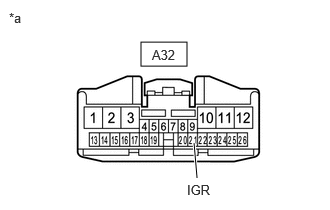
A436064C47
1.469,0.438 1.948,0.688 0.479,0.25 2.021,1.49 2.052,1.854 true 0.094,0.104 0.406,0.302 0.313,0.198 10 false *a 1.948,1.896 2.333,2.115 0.385,0.219 10 false IGR 1.583,0.49 2.031,0.667 0.448,0.177 10 false A32
*a Front view of wire harness connector
(to Engine Stop and Start ECU)


a.

Disconnect the engine stop and start ECU connector.


b.

Turn the ignition switch to ON.


c.

Measure the voltage according to the value(s) in the table below.

Standard Voltage:
Tester Connection Condition Specified Condition
A32-21 (IGR) - Body ground Ignition switch ON 9.5 to 14 V


Result:
Proceed to
OK
NG


OK

16.CHECK HARNESS AND CONNECTOR (+B AND IGP TERMINALS POWER SOURCE CIRCUIT)

NG

REPAIR OR REPLACE HARNESS OR CONNECTOR (ENGINE STOP AND START ECU - INSTRUMENT PANEL JUNCTION BLOCK ASSEMBLY (IGR NO. 2 RELAY))

16.CHECK HARNESS AND CONNECTOR (+B AND IGP TERMINALS POWER SOURCE CIRCUIT)
A399107C29
1.813,0.75 2.26,1 0.448,0.25 4.729,0.615 5.188,0.865 0.458,0.25 1.031,2.156 1.115,1.542 true 4.615,2.167 4.667,1.802 true 0.219,0.198 0.531,0.396 0.313,0.198 10 false *a 1.917,0.802 2.229,1 0.313,0.198 10 false A34 0.896,2.208 1.208,2.406 0.313,0.198 10 false +B 4.531,2.219 4.844,2.417 0.313,0.198 10 false IGP 4.833,0.656 5.271,0.844 0.438,0.188 10 false A32
*a Front view of wire harness connector
(to Engine Stop and Start ECU)
- -


a.

Disconnect the engine stop and start ECU connectors.


b.

Turn the ignition switch to ON.


c.

Measure the voltage according to the value(s) in the table below.

Standard Voltage:
Tester Connection Condition Specified Condition
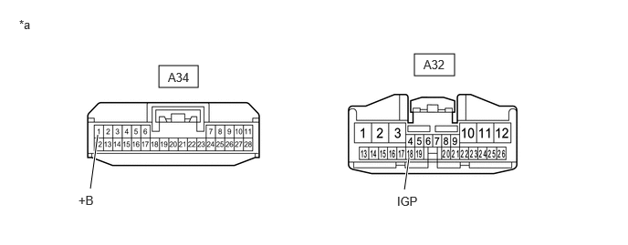
A34-1 (+B) - Body ground Ignition switch ON 9.5 to 14 V
A32-18 (IGP) - Body ground Ignition switch ON 9.5 to 14 V


Result:
Proceed to
OK
NG


OK

17.CHECK HARNESS AND CONNECTOR (ENGINE STOP AND START ECU - BODY GROUND)

NG

REPAIR OR REPLACE HARNESS OR CONNECTOR (ENGINE STOP AND START ECU - EFi-MAIN NO. 1 RELAY OR IGP RELAY)

17.CHECK HARNESS AND CONNECTOR (ENGINE STOP AND START ECU - BODY GROUND)
a.

Disconnect the engine stop and start ECU connectors.


b.

Measure the resistance according to the value(s) in the table below.

Standard Resistance:
Tester Connection Condition Specified Condition
A33-2 (GND2) - Body ground Always Below 1 Ω
A33-8 (GND1) - Body ground Always Below 1 Ω
A34-6 (DGND) - Body ground Always Below 1 Ω


Result:
Proceed to
OK
NG


OK

18.CHECK HARNESS AND CONNECTOR (ENGINE STOP AND START ECU - ST NO. 1 RELAY)

NG

REPAIR OR REPLACE HARNESS OR CONNECTOR

18.CHECK HARNESS AND CONNECTOR (ENGINE STOP AND START ECU - ST NO. 1 RELAY)
a.

Disconnect the engine stop and start ECU connector.


b.

Remove the ST NO. 1 relay from the No. 1 engine room relay block and No. 1 junction block assembly.


c.

Disconnect the certification ECU (smart key ECU assembly) connector. (w/ Smart Entry and Start System)


d.

Disconnect the ECM connector.


e.

Measure the resistance according to the value(s) in the table below.

Standard Resistance:
Tester Connection Condition Specified Condition
A34-21 (STA) - 2 (ST NO. 1 relay) Always Below 1 Ω
A34-21 (STA) or 2 (ST NO. 1 relay) - Body ground and other terminals Always 10 kΩ or higher


Result:
Proceed to
OK
NG


OK

NG

REPAIR OR REPLACE HARNESS OR CONNECTOR

19.PERFORM ACTIVE TEST USING GTS (STARTER(HOOD CLOSE))
a.

Check that the engine hood is closed.


b.

Connect the GTS to the DLC3.


c.

Turn the ignition switch to ON.


d.

Turn the GTS on.


e.

Enter the following menus: Powertrain / Stop and Start / Active Test / Starter(Hood Close).

Powertrain > Stop and Start > Active Test
Tester Display
Starter(Hood Close)
50004 392 42017

f.

Check whether the engine cranks while the Active Test "Starter(Hood Close)" is being performed.

NOTICE:

The Active Test "Starter(Hood Close)" is stopped automatically 3 seconds after the starter assembly begins operating.


Standard:

Engine cranks


Result:
Result Proceed to
Engine cranks A
Engine does not crank B


A

20.READ VALUE USING GTS (NEUTRAL SWITCH)

B

27.CHECK ENGINE STOP AND START ECU (STA SIGNAL)
20.READ VALUE USING GTS (NEUTRAL SWITCH)
a.

Connect the GTS to the DLC3.


b.

Turn the ignition switch to ON.


c.

Turn the GTS on.


d.

Enter the following menus: Powertrain / Stop and Start / Data List / Neutral Switch.

Powertrain > Stop and Start > Data List
Tester Display
Neutral Switch
50003 392 202

e.

In accordance with the display on the GTS, read the Data List.

OK:
GTS Display Condition Normal Condition
Neutral Switch Shift lever in P or N ON
Shift lever not in P or N OFF


Result:
Result Proceed to
NG A
OK (w/ Smart Entry and Start System) B
OK (w/o Smart Entry and Start System) C


A

B

21.CHECK HARNESS AND CONNECTOR (CERTIFICATION ECU (SMART KEY ECU ASSEMBLY) - ST NO. 1 RELAY, ECM)

C

23.INSPECT RELAY (ST NO. 2 RELAY)
21.CHECK HARNESS AND CONNECTOR (CERTIFICATION ECU (SMART KEY ECU ASSEMBLY) - ST NO. 1 RELAY, ECM)
a.

Disconnect the certification ECU (smart key ECU assembly) connector.


b.

Disconnect the engine stop and start ECU connector.


c.

Remove the ST NO. 1 relay from the No. 1 engine room relay block and No. 1 junction block assembly.


d.

Disconnect the ECM connector.


e.

Measure the resistance according to the value(s) in the table below.

Standard Resistance:
Tester Connection Condition Specified Condition
A126-9 (STAR) - 2 (ST NO. 1 relay) Always Below 1 Ω
A126-20 (STA) - A125-81 (PPOS) Always Below 1 Ω
A126-9 (STAR) or 2 (ST NO. 1 relay) - Body ground and other terminals Always 10 kΩ or higher
A126-20 (STA) or A125-81 (PPOS) - Body ground and other terminals Always 10 kΩ or higher


Result:
Proceed to
OK
NG


OK

22.READ VALUE USING GTS (STARTER START JUDGMENT SIGNAL)

NG

REPAIR OR REPLACE HARNESS OR CONNECTOR

22.READ VALUE USING GTS (STARTER START JUDGMENT SIGNAL)
a.

Connect the GTS to the DLC3.


b.

Turn the ignition switch to ON.


c.

Turn the GTS on.


d.

Enter the following menus: Powertrain / Engine / Data List / Starter Start Judgment Signal.

Powertrain > Engine > Data List
Tester Display
Starter Start Judgment Signal
50003 372 1888

e.

In accordance with the display on the GTS, read the Data List.

OK:
GTS Display Condition Normal Condition
Starter Start Judgment Signal Shift lever in P or N 1
Shift lever not in P or N 0


Result:
Proceed to
OK
NG


OK

NG

23.INSPECT RELAY (ST NO. 2 RELAY)

OK

24.CHECK HARNESS AND CONNECTOR (ST NO. 1 RELAY - ST NO. 2 RELAY - IGNITION OR STARTER SWITCH ASSEMBLY)

NG

REPLACE RELAY (ST NO. 2 RELAY)

24.CHECK HARNESS AND CONNECTOR (ST NO. 1 RELAY - ST NO. 2 RELAY - IGNITION OR STARTER SWITCH ASSEMBLY)
A436055C01
0.115,0.063 0.396,0.302 0.281,0.24 10 false *1 2.135,1.823 2.417,2.063 0.281,0.24 10 false *2 2.146,0.344 2.427,0.583 0.281,0.24 10 false *3
*1 No. 1 Engine Room Relay Block and No. 1 Junction Block Assembly
*2 ST NO. 1 relay
*3 ST NO. 2 Relay


a.

Remove the ST NO. 1 relay and ST NO. 2 relay from the No. 1 engine room relay block and No. 1 junction block assembly.


b.

Disconnect the ignition or starter switch assembly connector.


c.

Disconnect the engine stop and start ECU connector.


d.

Disconnect the ECM connector.


e.

Measure the resistance according to the value(s) in the table below.

Standard Resistance:
Tester Connection Condition Specified Condition
G28-5 (ST1) - 5 (ST NO. 2 relay) Always Below 1 Ω
3 (ST NO. 2 relay) - 2 (ST NO. 1 relay) Always Below 1 Ω
G28-5 (ST1) or 5 (ST NO. 2 relay) - Body ground and other terminals Always 10 kΩ or higher
3 (ST NO. 2 relay) or 2 (ST NO. 1 relay) - Body ground and other terminals Always 10 kΩ or higher


Result:
Proceed to
OK
NG


OK

25.INSPECT IGNITION OR STARTER SWITCH ASSEMBLY

NG

REPAIR OR REPLACE HARNESS OR CONNECTOR

25.INSPECT IGNITION OR STARTER SWITCH ASSEMBLY

OK

26.CHECK HARNESS AND CONNECTOR (ST NO. 2 RELAY - ECM)

NG

26.CHECK HARNESS AND CONNECTOR (ST NO. 2 RELAY - ECM)
a.

Remove the ST NO. 2 relay from the No. 1 engine room relay block and No. 1 junction block assembly.


b.

Disconnect the ECM connector.


c.

Measure the resistance according to the value(s) in the table below.

Standard Resistance:
Tester Connection Condition Specified Condition
C71-32 (NSR+) - 2 (ST NO. 2 relay) Always Below 1 Ω
C71-33 (NSR-) - 1 (ST NO. 2 relay) Always Below 1 Ω
C71-32 (NSR+) or 2 (ST NO. 2 relay) - Body ground and other terminals Always 10 kΩ or higher
C71-33 (NSR-) or 1 (ST NO. 2 relay) - Body ground and other terminals Always 10 kΩ or higher


Result:
Proceed to
OK
NG


OK

NG

REPAIR OR REPLACE HARNESS OR CONNECTOR

27.CHECK ENGINE STOP AND START ECU (STA SIGNAL)
A419453C46
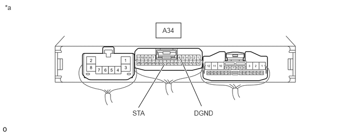
3.25,0.479 3.771,0.792 0.521,0.313 4.198,2.219 3.76,1.229 true 2.885,2.25 3.427,1.344 true 2.76,2.281 3.542,2.479 0.781,0.198 10 false STA 4.042,2.281 4.698,2.469 0.656,0.188 10 false DGND 3.385,0.552 3.76,0.75 0.375,0.198 10 false A34 0.104,0.073 0.885,0.271 0.781,0.198 10 false *a
*a Component with harness connected
(Engine Stop and Start ECU)
- -


a.

Measure the voltage according to the value(s) in the table below.

Standard Voltage:
Tester Connection Condition Specified Condition
A34-21 (STA) - A34-6 (DGND) Engine start 6 to 14 V


Result:
Proceed to
OK
NG


OK

28.INSPECT RELAY (ST NO. 1 RELAY)

NG

14.CHECK HARNESS AND CONNECTOR (BIN1 AND BIN2 TERMINALS POWER SOURCE CIRCUIT)
28.INSPECT RELAY (ST NO. 1 RELAY)

OK

29.CHECK HARNESS AND CONNECTOR (ST NO. 1 RELAY - BATTERY)

NG

REPLACE RELAY (ST NO. 1 RELAY)

29.CHECK HARNESS AND CONNECTOR (ST NO. 1 RELAY - BATTERY)
A435792C01
0.094,0.063 0.406,0.219 0.313,0.156 10 false *1 2.125,1.188 2.438,1.344 0.313,0.156 10 false *2
*1 No. 1 Engine Room Relay Block and No. 1 Junction Block Assembly
*2 ST NO. 1 Relay


a.

Remove the ST NO. 1 relay from the No. 1 engine room relay block and No. 1 junction block assembly.


b.

Measure the voltage according to the value(s) in the table below.

Standard Voltage:
Tester Connection Condition Specified Condition
5 (ST NO. 1 relay) - Body ground Always 9.5 to 14 V


Result:
Proceed to
OK
NG


OK

30.CHECK HARNESS AND CONNECTOR (ST NO. 1 RELAY - STARTER ASSEMBLY)

NG

REPAIR OR REPLACE HARNESS OR CONNECTOR (ST NO. 1 RELAY - BATTERY)

30.CHECK HARNESS AND CONNECTOR (ST NO. 1 RELAY - STARTER ASSEMBLY)
a.

Remove the ST NO. 1 relay from the No. 1 engine room relay block and No. 1 junction block assembly.


b.

Disconnect the starter assembly connector.


c.

Measure the resistance according to the value(s) in the table below.

Standard Resistance:
Tester Connection Condition Specified Condition
3 (ST NO. 1 relay) - C43-2 (SL1) Always Below 1 Ω


Result:
Proceed to
OK
NG


OK

31.CHECK HARNESS AND CONNECTOR (ST NO. 1 RELAY - BODY GROUND)

NG

REPAIR OR REPLACE HARNESS OR CONNECTOR (ST NO. 1 RELAY - STARTER ASSEMBLY)

31.CHECK HARNESS AND CONNECTOR (ST NO. 1 RELAY - BODY GROUND)
a.

Remove the ST NO. 1 relay from the No. 1 engine room relay block and No. 1 junction block assembly.


b.

Measure the resistance according to the value(s) in the table below.

Standard Resistance:
Tester Connection Condition Specified Condition
1 (ST NO. 1 relay) - Body ground Always Below 1 Ω


Result:
Proceed to
OK
NG


OK

32.CHECK HARNESS AND CONNECTOR (ENGINE STOP AND START ECU - ST NO. 1 RELAY)

NG

REPAIR OR REPLACE HARNESS OR CONNECTOR (ST NO. 1 RELAY - BODY GROUND)

32.CHECK HARNESS AND CONNECTOR (ENGINE STOP AND START ECU - ST NO. 1 RELAY)
a.

Disconnect the engine stop and start ECU connector.


b.

Remove the ST NO. 1 relay from the No. 1 engine room relay block and No. 1 junction block assembly.


c.

Disconnect the certification ECU (smart key ECU assembly) connector. (w/ Smart Entry and Start System)


d.

Measure the resistance according to the value(s) in the table below.

Standard Resistance:
Tester Connection Condition Specified Condition
A34-21 (STA) - 2 (ST NO. 1 relay) Always Below 1 Ω
A34-21 (STA) or 2 (ST NO. 1 relay) - Body ground and other terminals Always 10 kΩ or higher


Result:
Proceed to
OK
NG


OK

33.CHECK HARNESS AND CONNECTOR (STARTER ASSEMBLY - BATTERY)

NG

REPAIR OR REPLACE HARNESS OR CONNECTOR

33.CHECK HARNESS AND CONNECTOR (STARTER ASSEMBLY - BATTERY)
A434147C01
1.167,0.771 0.542,1.021 0.542,1.021 0.406,1.031 true 0.188,0.104 0.417,0.365 0.229,0.26 10 false *1 0.167,0.99 0.396,1.25 0.229,0.26 10 false *a
*1 Starter Assembly
*a D1-1 (B)


a.

Measure the voltage according to the value(s) in the table below.

Standard Voltage:
Tester Connection Condition Specified Condition
D1-1 (B) - Body ground Always 9.5 to 14 V


NOTICE:

Before performing this step, check that the starter assembly connector D1 is not disconnected or loose.


Result:
Proceed to
OK
NG


OK

34.CHECK STARTER SIGNAL (OUTPUT WAVEFORM)

NG

REPAIR OR REPLACE HARNESS OR CONNECTOR

34.CHECK STARTER SIGNAL (OUTPUT WAVEFORM)
a.

Connect the positive (+) lead of an oscilloscope to the positive (+) battery terminal and the negative (-) lead to the negative (-) battery terminal.


b.

While cranking the engine, count the number of times the waveform drops.
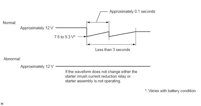
A285237E05
3.438,0.781 3.583,0.417 3.583,0.417 3.833,0.417 false 0.104,0.729 0.719,0.927 0.615,0.198 10 false Normal: 0.125,2.031 0.844,2.229 0.719,0.198 10 false Abnormal: 0.719,0.917 2.042,1.135 1.323,0.219 10 false Approximately 12 V 1.938,1.24 3.927,1.438 1.99,0.198 10 false 7.6 to 9.3 V* 3.906,0.323 5.667,0.542 1.76,0.219 10 false Approximately 0.1 seconds 3.396,1.698 5.073,1.896 1.677,0.198 10 false Less than 3 seconds 5.167,3.177 7.083,3.5 1.917,0.323 10 false *: Varies with battery condition 2.323,2.49 4.958,3.042 2.635,0.552 10 false If the waveform does not change either the starter inrush current reduction relay or starter assembly is not operating. 0.729,2.302 2.052,2.521 1.323,0.219 10 false Approximately 12 V

Standard:

Waveform drops 2 times


Result:
Number of Times Waveform Dropped Proceed to
0 times A
2 times B


A

35.INSPECT STARTER INRUSH CURRENT REDUCTION RELAY

B

38.INSPECT STARTER ASSEMBLY
35.INSPECT STARTER INRUSH CURRENT REDUCTION RELAY
A434144C02
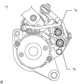
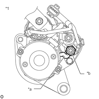
2.375,1.333 2.729,0.427 2.729,0.427 2.938,0.427 true 2.458,1.771 2.74,2.833 2.74,2.833 2.875,2.833 true 0.208,0.208 0.448,0.49 0.24,0.281 10 false *1 3.021,0.333 3.26,0.615 0.24,0.281 10 false *a 2.969,2.75 3.208,3.031 0.24,0.281 10 false *b
*1 Starter Assembly
*a B Terminal
*b M Terminal


a.

Disconnect the cable from the negative (-) battery terminal.


b.

Disconnect terminals B and M of the starter inrush current reduction relay.


c.

Measure the resistance according to the value(s) in the table below.

Standard Resistance:
Tester Connection Condition Specified Condition
B Terminal - M Terminal Always Below 1 Ω


Result:
Proceed to
OK
NG


OK

36.INSPECT STARTER ASSEMBLY (WIRE HARNESS)

NG

37.INSPECT STARTER ASSEMBLY (M TERMINAL)
36.INSPECT STARTER ASSEMBLY (WIRE HARNESS)
A434145C02
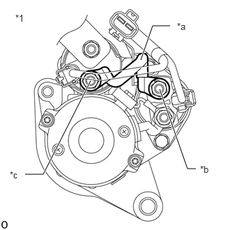
2.104,0.896 2.281,0.385 2.281,0.385 2.542,0.385 true 2.385,1.333 2.802,2.521 2.802,2.521 2.927,2.521 true 1.354,1.208 0.646,2.604 0.646,2.604 0.375,2.604 true 0.229,0.188 0.479,0.479 0.25,0.292 10 false *1 2.646,0.313 2.958,0.51 0.313,0.198 10 false *a 2.99,2.448 3.302,2.646 0.313,0.198 10 false *b 0.146,2.531 0.458,2.729 0.313,0.198 10 false *c
*1 Starter Assembly
*a Inspect Part
*b B Terminal
*c M Terminal


a.

Disconnect the cable from the negative (-) battery terminal.


b.

Disconnect terminal B of the starter inrush current reduction relay.


c.

Disconnect terminal M of the starter assembly.


d.

Measure the resistance according to the value(s) in the table below.

Standard Resistance:
Tester Connection Condition Specified Condition
M Terminal - B Terminal Always Below 1 Ω


Result:
Proceed to
OK
NG


OK

NG

REPAIR OR REPLACE WIRE HARNESS

37.INSPECT STARTER ASSEMBLY (M TERMINAL)
A434146C02
1.177,3.083 1.406,3.083 1.406,3.083 2.25,1.948 true 2.927,2.563 2.792,2.563 2.792,2.563 2.458,1.76 true 0.188,0.208 0.438,0.521 0.25,0.313 10 false *1 0.969,3.01 1.219,3.323 0.25,0.313 10 false *a 3.01,2.458 3.26,2.771 0.25,0.313 10 false *b
*1 Starter Assembly
*a Inspect Part
*b M Terminal


a.

Disconnect the cable from the negative (-) battery terminal.


b.

Disconnect terminal M of the starter inrush current reduction relay.


c.

Measure the resistance according to the value(s) in the table below.

Standard Resistance:
Tester Connection Condition Specified Condition
M Terminal - Body ground Always Below 1 Ω


Result:
Proceed to
OK
NG


OK

NG