M20D-FKS ENGINE CONTROL SFI SYSTEM VEHICLE CONTROL HISTORY
DESCRIPTION (SFI SYSTEM)
Vehicle Control History is a function that captures and stores ECU data when triggered by specific vehicle behavior.
If the customer states that the engine stalled or will not start, it may be possible to diagnose the cause of the malfunction by checking the vehicle history information and freeze frame data.
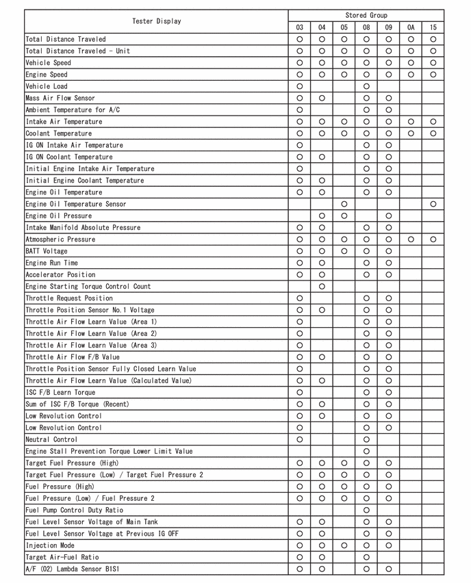
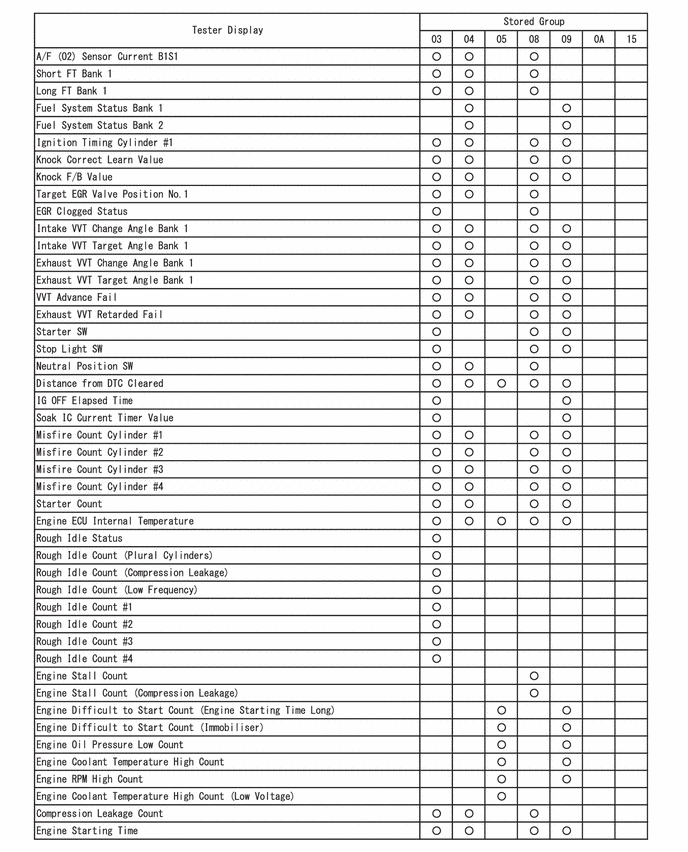
The number of possible stored Freeze Frame Data sets, whether multi Freeze Frame Data is available, the number of freeze frame points, Freeze Frame Data items, the ECU internal range, etc., is different depending on the stored group.
The stored data items for Vehicle Control History Freeze Frame Data are different depending on the stored group. When the value of a data item does not change across all points, only the value of the detection point will be displayed. The content of the Freeze Frame Data is almost the same as that of the Data List.
PRECAUTIONS (SFI SYSTEM)
As Vehicle Control History may be overwritten whenever the trigger conditions are met, make sure to save Vehicle Control History before performing any inspections.
As Vehicle Control History may be stored when performing an Active Test, learning, etc., make sure to clear the Vehicle Control History before returning the vehicle to the customer.
CHECK VEHICLE CONTROL HISTORY (SFI SYSTEM)
Connect the GTS to the DLC3.
Turn the ignition switch to ON.
Turn the GTS on.
Enter the following menus: Powertrain / Engine / Utility / Vehicle Control History (RoB).
- Powertrain > Engine > Utility
-
Tester Display Vehicle Control History (RoB) - 50005 372 55
- HINT:
-
It is also possible to display Vehicle Control History during the Health Check, if "Store All Data" is selected.
| Code | Item | Trigger Description | Stored Group | Reference Inspection Procedure | Link |
|---|---|---|---|---|---|
| X0800 | Engine Stall | Detection Condition (Engine Stall)
·
Prerequisite Conditions: The engine is running (after engine is judged to be difficult to start) ·
Detection Conditions: The engine speed is decreases to 200 rpm or less, or stops ·
Duration: 0.5 seconds or more |
08 | Flowchart [Engine Stalls] step 3 | ( 202304,999999,_51,_083058,_0401834,RM1000000029CAS,) 202304,999999,_51,_083058,_0401834,RM1000000029CAS,)
|
| The engine stalled due to factors other than the operation of the ignition switch | |||||
| X0803 | Engine Stall (Compression Leakage) | It is judged that the engine stalled due to compression leakage | 08 | Flowchart [Engine Stalls] step 3 | (202304,999999,_51,_083058,_0401834,RM1000000029CAS,)
|
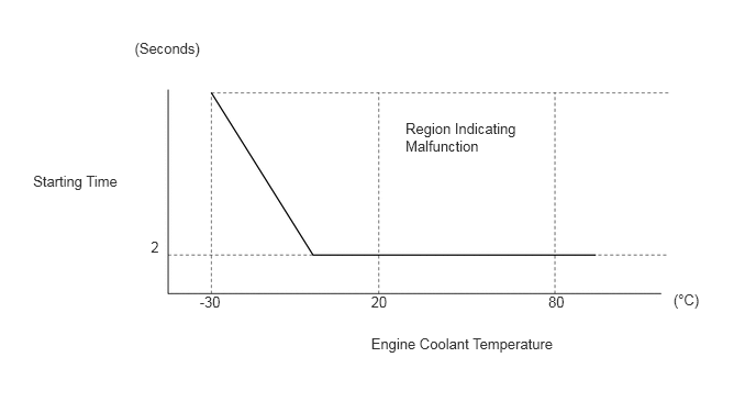
| X0810 | Engine Difficult to Start (Engine Starting Time Long) | Detection Condition (Engine Starting Time Long)
·
Prerequisite Conditions: STA signal is ON ·
Detection Conditions: The engine speed is less than 500 rpm for a long period of time (the starting time is long or the engine does not start) ·
Duration: Refer to Engine Difficult to Start Duration Judgment Region illustration |
09 | Flowchart [Engine Difficult to Start] step 3 | (202304,999999,_51,_083058,_0401834,RM1000000029CAR,)
|
| The engine speed decreases or the engine stalls immediately after starting | |||||
| X0811 | Engine Difficult to Start (Engine Stall Immediately After Starting) | Detection Condition (Engine Stall Immediately After Starting)
·
Prerequisite Conditions: Within 2 seconds after the engine has started (engine speed is 500 rpm or more) and the engine coolant temperature is -15°C (5°F) or more ·
Detection Conditions: The engine speed decreases to 200 rpm or less (immediately after starting, the engine speed decreases or the engine stalls) ·
Duration: - |
09 | Flowchart [Engine Difficult to Start] step 3 | (202304,999999,_51,_083058,_0401834,RM1000000029CAR,)
|
| The engine speed decreases or the engine stalls immediately after starting | |||||
| X0812 | Engine Difficult to Start (Immobiliser) | Engine difficult to start due to immobiliser | 09 | Flowchart [Engine Difficult to Start] step 3 | (202304,999999,_51,_083058,_0401834,RM1000000029CAR,)
|
| X0821 | Rough Idle #1 | Detection Condition (Rough Idle)
·
Prerequisite Conditions: The engine is idling with the vehicle is stopped and the accelerator pedal is fully released ·
Detection Conditions: It is judged that combustion is unstable due to the instantaneous change in engine speed for each cylinder ·
Duration: Depending on the combustion status, between 2 and 10 seconds |
03 | Flowchart [Rough Idling] step 3 | (201910,999999,_51,_083058,_0401834,RM100000001JDWJ,)
|
| Idling is rough due to unstable combustion in the No. 1 cylinder | |||||
| X0822 | Rough Idle #2 | Idling is rough due to unstable combustion in the No. 2 cylinder | 03 | Flowchart [Rough Idling] step 3 | (201910,999999,_51,_083058,_0401834,RM100000001JDWJ,)
|
| X0823 | Rough Idle #3 | Idling is rough due to unstable combustion in the No. 3 cylinder | 03 | Flowchart [Rough Idling] step 3 | (201910,999999,_51,_083058,_0401834,RM100000001JDWJ,)
|
| X0824 | Rough Idle #4 | Idling is rough due to unstable combustion in the No. 4 cylinder | 03 | Flowchart [Rough Idling] step 3 | (201910,999999,_51,_083058,_0401834,RM100000001JDWJ,)
|
| X082A | Rough Idle (Plural Cylinders) | Idling is rough due to multiple cylinders
As more than one cylinder is affected, the EGR system, fuel system, etc. is suspected |
03 | Flowchart [Rough Idling] step 3 | (201910,999999,_51,_083058,_0401834,RM100000001JDWJ,)
|
| X082D | Rough Idle (Compression Leakage) | Idling is judged to be rough due to compression leakage | 03 | Flowchart [Rough Idling] step 3 | (201910,999999,_51,_083058,_0401834,RM100000001JDWJ,)
|
| X082E | Rough Idle (Low Frequency) | Slight rough idle symptoms are detected 3 times in 10 trips
|
03 | Flowchart [Rough Idling] step 3 | (201910,999999,_51,_083058,_0401834,RM100000001JDWJ,)
|
| X0844 | Engine Lack of Power | Detection Condition (Engine Lack of Power)
·
Prerequisite Conditions: All of the following conditions are met -
The accelerator opening angle 80% or more. -
The engine speed is 400 rpm or more. -
The intake air temperature is 80°C (176°F) or less. -
The atmospheric pressure is 61 kPa(abs) [8.70 psi(abs)] or higher. -
The STP signal is off. -
The STA signal is off. -
Shift lever is not in P or N. ·
Detects a condition where the output torque is insufficient approximately 65% or more relative to the requested torque (divided value of the output torque is approximately 0.35 less than the requested torque) ·
Duration: 2 seconds or more |
04 | Flowchart [Lack of Power] step 3 | (202304,999999,_51,_083058,_0401834,RM1000000029CAT,)
|
| X0845 | Engine Lack of Power (Bad Fuel Condition) | Engine output is insufficient due to bad quality fuel
(Fuel quality is bad due to fuel aging degradation, water intrusion or fuel additive) |
04 | Flowchart [Lack of Power] step 3 | (202304,999999,_51,_083058,_0401834,RM1000000029CAT,)
|
| X0850 | Engine Oil Pressure Low | The engine oil pressure is low | 05 | - | - |
| X0851 | Engine Coolant Temperature High | The engine coolant temperature is high (overheating) | 05 | - | - |
| X0852 | Engine RPM High | The engine speed is high (over revving) | 05 | - | - |
| X0854 | Engine Coolant Temperature High (Low Voltage) | The engine coolant temperature is high (overheating) due to a low engine water pump assembly voltage causing the engine water pump assembly to stop | 05 | - | - |
| X0855 | Oil Level Warning Request | When oil level warning light (indicator) is displayed (When the engine oil pressure reduces when air is sucked into the system during cornering and braking, etc) | 05 | - | - |
| X0856 | GPF Rejuvenate Interruption | When particulate filter rejuvenation stops | 15 | Check the Vehicle Control History Freeze Frame Data items "GPF Rejuvenate Impossibility History" | (202304,999999,_51,_083058,_0401834,RM1000000029C6L,)
|
| X0857 | GPF Rejuvenate Run Insufficiency | The air fuel ratio conditions are met at 60 km/h (37 mph) or more, but the temperature required for particulate filter regeneration has not been reached | 15 | Check that the vehicle was driven in the specified manner, and then increase the vehicle speed and perform particulate filter regeneration again.
Refer to Particulate Filter Regeneration Procedure |
(202304,999999,_51,_083058,_0401834,RM1000000029C6L,)
|
| X0858 | Particulate Filter Differential Pressure High Bank1 | When the GPF (Gasoline Particulate Filter) upstream exhaust pressure measured by the differential pressure sensor (GPF differential pressure calibration value) exceeds the threshold value due to the accumulation of PM or ash (metal oxide) | 0A | Refer to the P244B00 inspection procedure | (202304,999999,_51,_083058,_0401834,RM1000000029C9U,P244B00)
|
| X0859 | Particulate Filter Differential Pressure Too High Bank1 | When the GPF upstream exhaust pressure measured by the differential pressure sensor (GPF differential pressure calibration value) exceeds the threshold value due to further PM and ash being accumulated in the GPF after the GPF differential pressure sensor determines the pressure is high (X0858) | 0A | Refer to the P244B00 inspection procedure | (202304,999999,_51,_083058,_0401834,RM1000000029C9U,P244B00)
|
| X085C | Over Temperature Prevention when Particulate Filter Over Accumulation | When the PM deposition ratio is at or above the specified value and GPF temperature is at or above the specified value | 0A | Refer to Particulate Filter Regeneration Procedure | (202304,999999,_51,_083058,_0401834,RM1000000029C6L,)
|
| X085E | GPF/DPF Clogged Level 2 | When the customer has performed particulate filter regenerate | 15 | Refer to Particulate Filter Regeneration Procedure | (202304,999999,_51,_083058,_0401834,RM1000000029C6L,)
|
| XF01B | ECU Security Key Not Registered | ECU security key has not been updated | - | - | (202405,999999,_V1,_083041,_0402305,RM100000002ISNL,)
|
| Stored Group | Number of Records | Number of Freeze Frame Points | Multi Freeze Frame Data Sampling Period | Note |
|---|---|---|---|---|
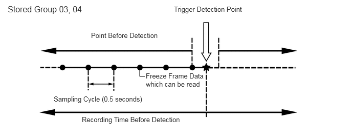
| 03 | 1 code
|
7 points (1 point at detection + 6 points before detection)
|
0.5 seconds | The data can be cleared by using the GTS or by disconnecting the cable from the negative (-) battery terminal. |
| 04 | 1 code
|
7 points (1 point at detection + 6 points before detection)
|
0.5 seconds | The data can be cleared by using the GTS or by disconnecting the cable from the negative (-) battery terminal. |
| 05 | 4 codes
|
1 point (multi freeze frame data not available) | - | ·
The data can be cleared by using the GTS. ·
The data cannot be cleared by disconnecting the cable from the negative (-) battery terminal. |
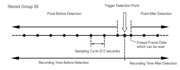
| 08 | 1 code
|
12 points (1 point at detection + 8 points before detection + 3 points after detection)
|
0.5 seconds | ·
The data can be cleared by using the GTS. ·
The data cannot be cleared by disconnecting the cable from the negative (-) battery terminal. |
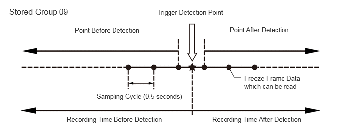
| 09 | 1 code
|
7 points (1 point at detection + 3 points before detection + 3 points after detection)
|
0.5 seconds | The data can be cleared by using the GTS or by disconnecting the cable from the negative (-) battery terminal. |
| 0A | 2 codes
|
1 point (multi Freeze Frame Data not available) | - | The data can be cleared by using the GTS or by disconnecting the cable from the negative (-) battery terminal. |
| 15 | 2 codes
|
1 point (multi Freeze Frame Data not available) | - | The data can be cleared by using the GTS or by disconnecting the cable from the negative (-) battery terminal. |
- HINT:
- ·
Multi Freeze Frame Data makes it possible to display the engine condition (ECU data) both before and after the trigger detection point.
·The number of available points differs depending on the stored group.
·When the value of a data item does not change across all points, only the value at the detection point will be displayed.
 2.948,1.552 2.844,1.552 2.844,1.552 2.844,1.385 false 0.156,0.083 2.917,0.323 2.76,0.24 12 false Stored Group 03, 04 1.854,0.635 3.458,0.906 1.604,0.271 10 false Point Before Detection 1.667,2.344 3.802,2.656 2.135,0.313 10 false Recording Time Before Detection 1.094,1.927 3.063,2.188 1.969,0.26 10 false Sampling Cycle (0.5 seconds) 3.542,0.104 5.135,0.396 1.594,0.292 10 false Trigger Detection Point 2.969,1.458 4.177,1.948 1.208,0.49 10 false Freeze Frame Data which can be read
 5.406,1.688 5.208,1.615 5.208,1.615 5.208,1.479 false 0.302,0.156 1.677,0.354 1.375,0.198 12 false Stored Group 08 4.156,0.135 5.677,0.323 1.521,0.188 10 false Trigger Detection Point 5.604,0.458 7,0.656 1.396,0.198 10 false Point After Detection 1.885,0.458 3.479,0.688 1.594,0.229 10 false Point Before Detection 2.979,1.958 4.885,2.229 1.906,0.271 10 false Sampling Cycle (0.5 seconds) 5.448,1.615 6.875,2.01 1.427,0.396 10 false Freeze Frame Data which can be read 1.542,2.417 3.667,2.656 2.125,0.24 10 false Recording Time Before Detection 5.167,2.448 7.135,2.677 1.969,0.229 10 false Recording Time After Detection
 5.063,1.625 4.927,1.625 4.927,1.625 4.833,1.458 false 3.302,0.177 5.073,0.396 1.771,0.219 10 false Trigger Detection Point 1.573,0.552 3.281,0.813 1.708,0.26 10 false Point Before Detection 4.833,0.542 6.594,0.75 1.76,0.208 10 false Point After Detection 2.031,1.948 4.115,2.198 2.083,0.25 10 false Sampling Cycle (0.5 seconds) 0.198,0.146 1.917,0.417 1.719,0.271 12 false Stored Group 09 5.135,1.563 6.375,2.104 1.24,0.542 10 false Freeze Frame Data which can be read 1.406,2.427 3.802,2.646 2.396,0.219 10 false Recording Time Before Detection 4.458,2.427 6.781,2.656 2.323,0.229 10 false Recording Time After Detection
-
Only 1 measurement point can be displayed for stored group 05, 0A and 15 Freeze Frame Data.
CLEAR VEHICLE CONTROL HISTORY (SFI SYSTEM)
Connect the GTS to the DLC3.
Turn the ignition switch to ON.
Turn the GTS on.
Enter the following menus: Powertrain / Engine / Utility / Vehicle Control History (RoB) (Clear).
- NOTICE:
-
By performing this procedure, all stored Vehicle Control History items will be cleared.
VEHICLE CONTROL HISTORY FREEZE FRAME DATA (SFI SYSTEM)
Connect the GTS to the DLC3.
Turn the ignition switch to ON.
Turn the GTS on.
Enter the following menus: Powertrain / Engine / Utility / Vehicle Control History (RoB).
Select a vehicle control history item to access the applicable freeze frame data.
Check the Freeze Frame Data recorded with the Vehicle Control History.

CHECK VEHICLE CONTROL HISTORY (CHARGING SYSTEM)
Connect the GTS to the DLC3.
Turn the ignition switch to ON.
Turn the GTS on.
Enter the following menus: Powertrain / Engine / Utility / Vehicle Control History (RoB).
- Powertrain > Engine > Utility
-
Tester Display Vehicle Control History (RoB) - 50005 372 55
| Code | Tester Display | Measurement Item | Diagnostic Note |
|---|---|---|---|
| X0600 | Auxiliary Battery Voltage Low at Start | History of low battery voltage at engine control system start | - |
| X0601 | Auxiliary Battery Voltage Low at IG OFF | History of low battery voltage when ignition switch off | - |
| X0602 | Auxiliary Battery Discharge at IG OFF | History of battery becoming discharged when ignition switch off | - |
| X0603 | Auxiliary Battery Discharge at Running | History of battery becoming discharged while vehicle being driven | - |
| X0606 | Auxiliary Battery Voltage Low during Running | History of drop in the battery voltage while vehicle being driven | - |
| X0607 | Auxiliary Battery Voltage High during Running | History of rise in the battery voltage while vehicle being driven | - |
CLEAR VEHICLE CONTROL HISTORY (CHARGING SYSTEM)
Connect the GTS to the DLC3.
Turn the ignition switch to ON.
Turn the GTS on.
Enter the following menus: Powertrain / Engine / Utility / Vehicle Control History (Clear).
- NOTICE:
-
By performing this procedure, all stored Vehicle Control History items will be cleared.
VEHICLE CONTROL HISTORY FREEZE FRAME DATA (CHARGING SYSTEM)
Connect the GTS to the DLC3.
Turn the ignition switch to ON.
Turn the GTS on.
Enter the following menus: Powertrain / Engine / Utility / Vehicle Control History (RoB).
- Powertrain > Engine > Utility
-
Tester Display Vehicle Control History (RoB) - 50005 372 55
Select a Vehicle Control History item to access the applicable Freeze Frame Data.
Check the Freeze Frame Data recorded with the Vehicle Control History.
| GTS Display | Description |
|---|---|
| Total Distance Traveled | Driving distance |
| Total Distance Traveled - Unit | Unit of driving distance |
| Initial Engine Battery Minimum Voltage | Minimum voltage at engine start |
| Alternator Voltage - Non Active Test | Requested voltage when the regulator forced operation is not executed |
| Alternator Output Duty Ratio | LIN terminal output (power generation rate) |
| Auxiliary Battery Voltage | Battery voltage
(+B1, +B2 terminal) |
| Auxiliary Battery Integrated Current | Battery capacity taking into account battery deterioration. |
| Smoothed Value of Auxiliary Battery Temperature | Calculated battery fluid temperature by battery state sensor assembly |
| Auxiliary Battery Internal Resistance | Internal resistance of battery |
| Auxiliary Battery Internal Resistance Accuracy | Information on accuracy of battery internal resistance
Low: Not measured Middle: Undefined High: Measured Disable: Initial value/malfunction |
| Auxiliary Battery Charge Rate | Battery charge percentage calculated by battery state sensor assembly |
| Auxiliary Battery Charging Rate Accuracy | Accuracy of battery charge percentage calculated by battery state sensor assembly |
| Auxiliary Battery Charging Capacity | Charge of battery calculated by battery state sensor assembly |
| Auxiliary Battery SOH Accuracy | Information on accuracy of battery capacity (SOH)
Low: Not learned Middle: Undefined High: Learning completed Disable: Initial value/malfunction |
| Auxiliary Battery Current | Battery current |
| Auxiliary Battery Charging Integrated Current | Battery charging integrated current from time battery was installed to present |
| Auxiliary Battery Discharging Integrated Current | Battery discharging integrated current from time battery was installed to present |
| Auxiliary Battery Integrated Thermal Load | Integrated thermal load from time battery was installed to present |
| Charging Control Mode | Charging control state |
| Average Vehicle Speed during Trip | Average vehicle speed after engine started during current trip |
| Auxiliary Battery Integrated Current during Trip | Integrated current of battery detected by battery state sensor assembly during current trip |
| Auxiliary Battery Charging Integrated Current when Trip before Last | Integrated current charged during the previous trip |
| Auxiliary Battery Discharging Integrated Current when Trip before Last | Integrated current discharged during the previous trip |
| Auxiliary Battery Capacity after IG ON | Battery capacity immediately after ignition switch turned to ON |
| Auxiliary Battery SOC at IG ON | Battery status of charge after ignition switch turned to ON |
| Auxiliary Battery Capacity after IG OFF | Battery capacity immediately after ignition switch turned off |
| Auxiliary Battery SOC at IG OFF | Battery status of charge after ignition switch turned off |
| Estimated Open Ended Auxiliary Battery Voltage when IG OFF | Estimated battery release voltage calculated when ignition switch is off by the battery state sensor assembly |
| Auxiliary Battery Average Current during IG OFF | Average current while parked (average value of current consumed from when the ignition switch is off until lit is ON) |
| IG OFF Time just before IG ON | Parking duration (duration from when the ignition switch is off until it is ON) |
| Auxiliary Battery Average Current when Auxiliary Battery Voltage Low (during IG OFF) | Average current when system judges that voltage is low while parked (average current value when the ignition switch is off until the system judges the voltage is low while parked) |
| IG OFF Time when Auxiliary Battery Voltage Low (during IG OFF) | Parking duration when system judges that voltage is low while parked (duration from when the ignition switch is off until the system judges the voltage is low while parked) |
| Elapsed Time during Auxiliary Battery Voltage Low | Elapsed time that battery voltage detected by battery state sensor assembly was below threshold |
| Status of Alternator Temperature High | High temperature due to heavy load on alternator |
| Alternator Max Output Accumulated Time during Trip | Accumulated time of alternator maximum output (duty: 100%) during single trip |
| Alternator Output Voltage | Voltage generated by alternator |
| Alternator Speed | Speed of alternator |
| Alternator Temperature | Temperature of alternator |
| Alternator Target Voltage | Voltage commanded to alternator |
| Communication Error with Alternator | LIN communication malfunction in alternator |
| LIN Communication Error with Auxiliary Battery Sensor | LIN communication malfunction in battery state sensor |
| Auxiliary Battery Average Current during IG OFF 1 Trip before | Average battery current when ignition switch off 1 trip before |
| Auxiliary Battery Average Current during IG OFF 2 Trip before | Average battery current when ignition switch off 2 trip before |
| Auxiliary Battery Average Current during IG OFF 3 Trip before | Average battery current when ignition switch off 3 trip before |
| Auxiliary Battery Average Current during IG OFF 4 Trip before | Average battery current when ignition switch off 4 trip before |
| Auxiliary Battery Average Current during IG OFF 5 Trip before | Average battery current when ignition switch off 5 trip before |
| Total Distance Up to 1 Trip before | Cumulative distance traveled 1 trip before |
| Total Distance Up to 2 Trip before | Cumulative distance traveled 2 trip before |
| Total Distance Up to 3 Trip before | Cumulative distance traveled 3 trip before |
| Total Distance Up to 4 Trip before | Cumulative distance traveled 4 trip before |
| Total Distance Up to 5 Trip before | Cumulative distance traveled 5 trip before |
| IG OFF Time before 1 trip | Number of days ignition switch was off 1 trip before |
| IG OFF Time before 2 trip | Number of days ignition switch was off 2 trip before |
| IG OFF Time before 3 trip | Number of days ignition switch was off 3 trip before |
| IG OFF Time before 4 trip | Number of days ignition switch was off 4 trip before |
| IG OFF Time before 5 trip | Number of days ignition switch was off 5 trip before |
| IG ON Time Up to 1 trip before | Time ignition switch was ON 1 trip before |
| IG ON Time Up to 2 trip before | Time ignition switch was ON 2 trip before |
| IG ON Time Up to 3 trip before | Time ignition switch was ON 3 trip before |
| IG ON Time Up to 4 trip before | Time ignition switch was ON 4 trip before |
| IG ON Time Up to 5 trip before | Time ignition switch was ON 5 trip before |
| Engine Run Time before 1 trip | Total time ignition switch was turned on during previous trip (1) |
| Engine Run Time before 2 trip | Total time ignition switch was turned on during previous trip (2) |
| Engine Run Time before 3 trip | Total time ignition switch was turned on during previous trip (3) |
| Engine Run Time before 4 trip | Total time ignition switch was turned on during previous trip (4) |
| Engine Run Time before 5 trip | Total time ignition switch was turned on during previous trip (5) |
| Average Engine Speed | Average engine speed after engine starts during the current trip |
VEHICLE CONTROL HISTORY (AIRBAG SYSTEM)
- HINT:
-
A part of the control history can be confirmed using the vehicle control history.