THEFT DETERRENT / KEYLESS ENTRY DIGITAL KEY SYSTEM All Door Entry Lock/Unlock Functions do not Operate, but Wireless Functions Operate
DESCRIPTION
When the digital key entry function does not operate, there may be a malfunction in the communication system between the certification ECU (smart key ECU assembly) and digital key ECU assembly, or in the digital key.
WIRING DIAGRAM
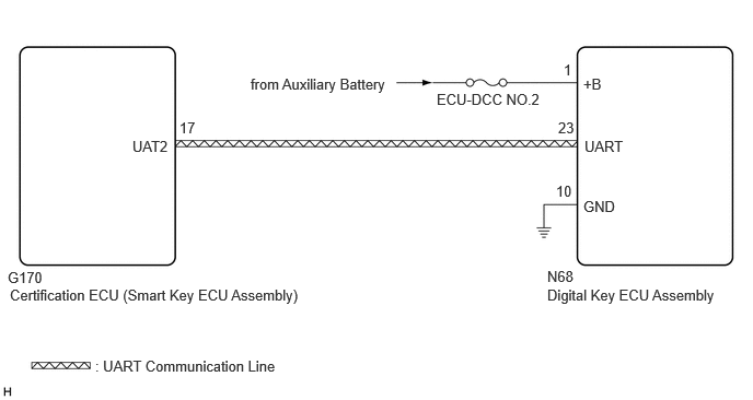
CAUTION / NOTICE / HINT
- NOTICE:
- ·
Before performing troubleshooting of the vehicle, refer to Precautions for Inspection or Registration to check for a cause of the malfunction which is not related to vehicle settings or vehicle components.
·Perform troubleshooting with the electrical key transmitter sub-assembly not inside the detection area of the smart entry and start system.
·When using the digital key to perform door lock/unlock with the entry function, refer to Precautions for Outside Vehicle Digital Key Detection Range/Diagnostic Range.
·Make sure that no DTCs are output. If any DTCs are output, proceed to Diagnostic Trouble Code Chart.
·If the digital key system has been disabled, enable the system before performing troubleshooting.
·Inspect the fuses for circuits related to this system before performing the following procedure.
·Cancel power saving mode before performing troubleshooting.
·Before replacing the certification ECU (smart key ECU assembly) or digital key ECU assembly, refer to Service Bulletin.
PROCEDURE
Select the setting by referring to the table below.
- Entry & Start
-
Tester Display Description Default Setting ECU Auto Entry Cancel Setting Function that enables or disables the smart entry and start system OFF $00:OFF,$01:ON Certification ECU (Smart key ECU assembly) Auto Entry Cancel 2 Setting Function that only prevents locking of the doors OFF $00:OFF,$04:ON Certification ECU (Smart key ECU assembly) - 50006 17
- Result:
Result Proceed to Smart entry and start system has not been canceled A Smart entry and start system has been canceled B
A
B
Check the smart entry and start system (for Entry Function).
- OK:
Smart entry and start system (for Entry Function) operates properly.
- Result:
Proceed to OK NG
OK
NG
Check whether it is possible to use the digital key to perform door lock/unlock with the entry function.
Check the entry unlock function (driver door, front passenger door).
Turn the ignition switch off.
Open and close the driver door.
From outside the vehicle, press the lock switch displayed on the digital key and lock all doors.
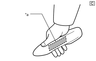
| *a | Unlock Sensor (Backside) |
The illustrations shown are examples only.
Hold the key in your hand and hold your hand inside the digital key detection range. Then grip the sensor on the reverse side of the door outside handle for 2 seconds or longer.*
*: Perform this step 3 seconds or more after performing step (3).
- NOTICE:
- ·
For details on the digital key detection range, refer to Precautions for Outside Vehicle Digital Key Detection Range/Diagnostic Range.
·Refer to Precautions for Inspection or Registration regarding the digital key and surrounding environment.
- HINT:
- ·
When checking the operation of the unlock sensor again, make sure to perform the procedure from step (1).
·Inspect the front passenger door using the same procedure.
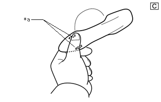
| *a | Lock Sensor |
The illustrations shown are examples only.
Check the entry lock function (driver door, front passenger door).
Turn the ignition switch off.
Open and close the driver door.
Hold the key in your hand and hold your hand inside the digital key detection range. Then touch the lock sensor on the surface of the door outside handle (indentation on the door outside handle) with multiple fingers for 2 seconds or longer.
- NOTICE:
- ·
For details on the digital key detection range, refer to Precautions for Outside Vehicle Digital Key Detection Range/Diagnostic Range.
·Refer to Precautions for Inspection or Registration regarding the digital key and surrounding environment.
- HINT:
- ·
If the door does not lock even when touching the lock sensor for 2 seconds or more, touch it with your palm.
·When checking the operation of the lock sensor again, make sure to perform the procedure from step (1).
·When checking the operation of the entry lock function several times, it can be operated up to 2 times consecutively. To operate the function 3 times or more consecutively, the doors need to be unlocked once. However, this is only for the entry lock function, other door lock operations, such as a wireless door lock operation can be performed consecutively.
·Inspect the front passenger door using the same procedure.
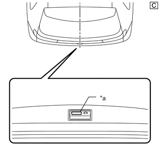
| *a | Back Door Opener Switch Assembly (Open Switch) |
The illustrations shown are examples only.
Check the entry back door open function.
With the back door closed and locked, hold the digital key in your hand and hold your hand inside the digital key detection range. Then operate the open switch.
- NOTICE:
- ·
For details on the digital key detection range, refer to Precautions for Outside Vehicle Digital Key Detection Range/Diagnostic Range.
·Refer to Precautions for Inspection or Registration regarding the digital key and surrounding environment.
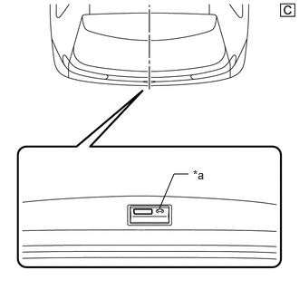
| *a | Back Door Opener Switch Assembly (Lock Switch) |
The illustrations shown are examples only.
Check the entry back door lock function.
With the back door closed and unlocked, hold the digital key in your hand and hold your hand inside the digital key detection range. Then operate the lock switch.
- NOTICE:
- ·
For details on the digital key detection range, refer to Precautions for Outside Vehicle Digital Key Detection Range/Diagnostic Range.
- ·
Refer to Precautions for Inspection or Registration regarding the digital key and surrounding environment.
Check the wireless function.
- Result:
Result Proceed to All door entry function and wireless function operate A All door entry function does not operate, but wireless function operates B All door entry function and wireless function do not operate C Entry function does not operate for one or more doors, but wireless function operates
A
B
C
Using the GTS, check for Vehicle Control History (RoB).
- Body Electrical > Entry&Start > Utility
-
Tester Display Vehicle Control History (RoB) - 50005 440 62
Take appropriate action in accordance with the result of the cause analysis.
- Result:
Proceed to NEXT
NEXT
- NOTICE:
-
With only one digital key connected to BLE, perform inspection in digital key diagnostic mode.
Check the front door outside handle assembly LH in digital key diagnostic mode.
Using the GTS, select Body Electrical / Entry&Start / Utility / Communication Check (Digital Key Diag Mode) / Digital key driver door outside area
- Body Electrical > Entry&Start > Utility
-
Tester Display Communication Check (Digital Key Diag Mode) - 50005 440 4806
Hold the digital key in your hand, and hold your hand inside the digital key detection range. Check that the buzzer sounds.
- NOTICE:
- ·
For details on the digital key detection range, refer to Precautions for Outside Vehicle Digital Key Detection Range/Diagnostic Range.
·Refer to Precautions for Inspection or Registration regarding the digital key and surrounding environment.
Check the front door outside handle assembly RH in digital key diagnostic mode.
Using the GTS, select Body Electrical / Entry&Start / Utility / Communication Check (Digital Key Diag Mode) / Digital key passenger door outside area
- Body Electrical > Entry&Start > Utility
-
Tester Display Communication Check (Digital Key Diag Mode) - 50005 440 4806
Hold the digital key in your hand, and hold your hand inside the digital key detection range. Check that the buzzer sounds.
- NOTICE:
- ·
For details on the digital key detection range, refer to Precautions for Outside Vehicle Digital Key Detection Range/Diagnostic Range.
·Refer to Precautions for Inspection or Registration regarding the digital key and surrounding environment.
Check the BLE luggage digital key receiver assembly in digital key diagnostic mode.
Using the GTS, select Body Electrical / Entry&Start / Utility / Communication Check (Digital Key Diag Mode) / Digital key back door/trunk lid outside area
- Body Electrical > Entry&Start > Utility
-
Tester Display Communication Check (Digital Key Diag Mode) - 50005 440 4806
Hold the digital key in your hand, and hold your hand inside the digital key detection range. Check that the buzzer sounds.
- NOTICE:
- ·
For details on the digital key detection range, refer to Precautions for Outside Vehicle Digital Key Detection Range/Diagnostic Range.
·Refer to Precautions for Inspection or Registration regarding the digital key and surrounding environment.
- Result:
Result Proceed to The buzzer sounds in all operation ranges A The buzzer fails to sound in all operation ranges B The buzzer does not sound in a particular operation range C
A
B
C
Check if there is digital key available that is already registered to the vehicle.
- Result:
Result Proceed to Another registered digital key is not available A Another registered digital key is available B
A
B
Check if another vehicle equipped with digital key system is available.
- Result:
Result Proceed to Vehicle equipped with digital key system not available A Vehicle equipped with digital key system available B
A
B
Register a share key.
- HINT:
-
Refer to the digital key application.
- Result:
Proceed to NEXT
NEXT
Using another registered digital key, check whether the entry function operates.
- NOTICE:
- ·
For details on the digital key detection range, refer to Precautions for Outside Vehicle Digital Key Detection Range/Diagnostic Range.
·Refer to Precautions for Inspection or Registration regarding the digital key and surrounding environment.
- OK:
Entry function operates.
- Result:
Proceed to OK NG
OK
NG
Using an oscilloscope, check the waveform.
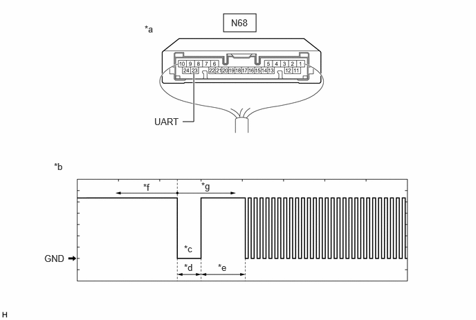
| *a | Component with harness connected
(Digital Key ECU Assembly) |
*b | Waveform |
| *c | Wakeup signal from digital key ECU assembly | *d | Approximately 15 ms. |
| *e | 15 to 50 ms. | *f | Before door lock/unlock operation using digital key |
| *g | After door lock/unlock operation using digital key | - | - |
- NOTICE:
-
The waveform shown in the illustration is an example for reference only. Noise, chattering, etc. are not shown.
- OK:
Tester Connection Condition Tool Setting Specified Condition N68-23 (UART) - Body ground All of the following conditions are met:
·Ignition switch off
·Door lock/unlock operation has been not performed via digital key → performed
2 V/DIV., 20 ms./DIV. Pulse generation
(See waveform)
- Result:
Result Proceed to OK (Normal Waveform) A NG (No Wakeup Signal) B NG (Normal Waveform Not Output) C NG (Stuck Low) D
A
B
C
D
Replace the digital key ECU assembly with a new one.
- HINT:
-
Refer to Service Bulletin.
- Result:
Proceed to NEXT
NEXT
Register the digital key code to the digital key ECU assembly.
- HINT:
-
Refer to Service Bulletin.
- Result:
Proceed to NEXT
NEXT
Register the owner key using the original digital key.
- HINT:
-
Refer to the digital key application.
- Result:
Proceed to NEXT
NEXT
Using another registered digital key, check whether the entry function operates.
- NOTICE:
- ·
For details on the digital key detection range, refer to Precautions for Outside Vehicle Digital Key Detection Range/Diagnostic Range.
·Refer to Precautions for Inspection or Registration regarding the digital key and surrounding environment.
- OK:
Entry function operates.
- Result:
Proceed to OK NG
OK
NG
Disconnect the N68 digital key ECU assembly connector.
Measure the voltage according to the value(s) in the table below.
- Standard Voltage:
Tester Connection Switch Condition Specified Condition N68-23 (UART) - Body ground Ignition switch off 11 to 14 V
- Result:
Proceed to OK NG
OK
NG
Take a digital key where the entry function does not operate, and register it as a share key of another vehicle equipped with the digital key system.
- HINT:
-
Refer to the digital key application.
- Result:
Proceed to NEXT
NEXT
Using the other vehicle equipped with the digital key system, check whether the entry function operates.
- NOTICE:
- ·
For details on the digital key detection range, refer to Precautions for Outside Vehicle Digital Key Detection Range/Diagnostic Range.
·Refer to Precautions for Inspection or Registration regarding the digital key and surrounding environment.
- OK:
The entry function operates.
- Result:
Proceed to OK NG
OK
NG