HEATING / AIR CONDITIONING AIR CONDITIONING UNIT(for M20D-FKS) REMOVAL
CAUTION / NOTICE / HINT
The necessary procedures (adjustment, calibration, initialization or registration) that must be performed after parts are removed, installed or replaced during the air conditioning unit assembly removal/installation are shown below.
| Replacement Part or Procedure | Necessary procedures | Effect/Inoperative Function when Necessary Procedure not Performed | Link |
|---|---|---|---|
·
No. 1 air conditioning radiator damper servo sub-assembly ·
No. 2 air conditioning radiator damper servo sub-assembly |
Servo motor initialization (Air conditioning system) | DTCs are stored | ( 202409,999999,_58,_083104,_0402828,RM100000002NSHC,) 202409,999999,_58,_083104,_0402828,RM100000002NSHC,)
|
- HINT:
-
When the cable is disconnected/reconnected to the auxiliary battery terminal, systems temporarily stop operating. However, each system has a function that completes learning the first time the system is used.
- ·
Learning completes when vehicle is driven
Effect/Inoperative Function when Necessary Procedures not Performed Necessary Procedures Link Stop and start system Drive the vehicle until stop and start control is permitted (approximately 5 to 60 minutes). ( 202409,999999,_51,_083056,_0402418,RM100000002NSFO,)
Lane tracing assist system Drive the vehicle straight ahead at 35 km/h (22 mph) or more for 5 second or more. ( 201910,999999,_58,_083101,_0401880,RM100000001JE9I,)
Pre-collision system
·Learning completes when vehicle is operated normally
Effect/Inoperative Function when Necessary Procedures not Performed Necessary Procedures Link *: w/ Power back door system
Power back door function* Fully close the back door by hand.
- HINT:
-
Initialization is not necessary if the above procedures are performed while the back door is closed.
( 202304,999999,_59,_083093,_0584672,RM1000000029PGT,)
Power door lock control system If the back door is locked and therefore cannot be opened, it is necessary to unlock the back door using the door control switch, electrical key transmitter sub-assembly switch. ( 202409,999999,_58,_083092,_0403003,RM100000002NS90,)
Air conditioning system After the ignition switch is turned to ON, the servo motor standard position is recognized -
PROCEDURE

 1. PRECAUTION
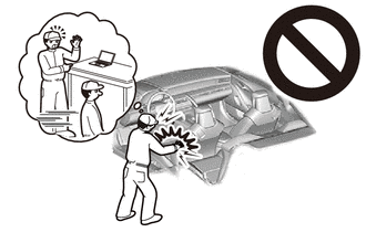
- CAUTION:
-
-
Be sure to read Precaution thoroughly before servicing.
- NOTICE:
-
After turning the ignition switch off, waiting time may be required before disconnecting the cable from the auxiliary negative (-) battery terminal.
2. ALIGN FRONT WHEELS FACING STRAIGHT AHEAD
3.DISCONNECT CABLE FROM NEGATIVE BATTERY TERMINAL
Click hereGeneral>MAINTENANCE>M20D-FKS BATTERY>REMOVAL202409,999999,_V1,_083136,_0403617,RM100000002NHPJ,
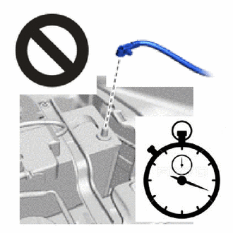
- CAUTION:
-
- ·
Wait at least 60 seconds after disconnecting the cable from the negative (-) auxiliary battery terminal to disable the SRS system.
·If the airbag deploys for any reason, it may cause a serious accident.
4.RECOVER REFRIGERANT FROM REFRIGERATION SYSTEM
5.DRAIN ENGINE COOLANT
6.REMOVE WINDSHIELD WIPER MOTOR AND LINK ASSEMBLY
55752
7.REMOVE COWL VENTILATOR SPLASH SHIELD
- HINT:
-
Remove using the same procedure that is performed when replacement of the cowl ventilator splash shield is necessary.
55704B
8.REMOVE COWL VENTILATOR PANEL SUB-ASSEMBLY
Detach the clamp.
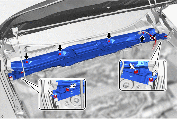

|
Bolt | 
|
Nut |
Remove the 4 bolts, 4 nuts and cowl ventilator panel sub-assembly.
9.REMOVE HOLE PLUG
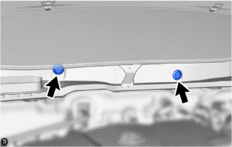
Remove the 2 hole plugs.
88707B
10.DISCONNECT SUCTION TUBE SUB-ASSEMBLY B
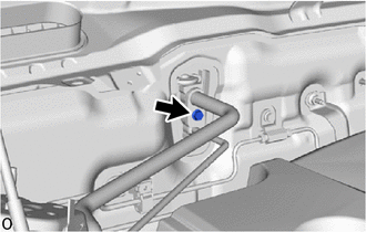
Remove the bolt.
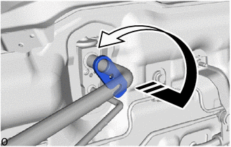

|
Rotate in this Direction |
Rotate the 1-point tightening plate as shown in the illustration.
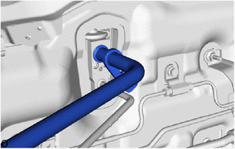
Disconnect the suction tube sub-assembly B.
- NOTICE:
-
Do not apply excessive force to the suction tube sub-assembly B.
Remove the O-ring from the suction tube sub-assembly B.
- NOTICE:
-
Seal the openings of the disconnected parts using vinyl tape to prevent entry of moisture and foreign matter.
88710E
11.DISCONNECT AIR CONDITIONING TUBE AND ACCESSORY ASSEMBLY
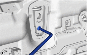
Disconnect the air conditioning tube and accessory assembly.
- NOTICE:
-
Do not apply excessive force to the air conditioning tube and accessory assembly.
Remove the O-ring from the air conditioning tube and accessory assembly.
- NOTICE:
-
Seal the openings of the disconnected parts using vinyl tape to prevent entry of moisture and foreign matter.
87246
12.DISCONNECT OUTLET HEATER WATER HOSE
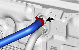
Using pliers, grip the claws of the clip and slide the clip to disconnect the outlet heater water hose.
- NOTICE:
- ·
Do not apply excessive force to the outlet heater water hose.
·Prepare a drain pan or cloth in case the coolant leaks.
87245
13.DISCONNECT INLET HEATER WATER HOSE
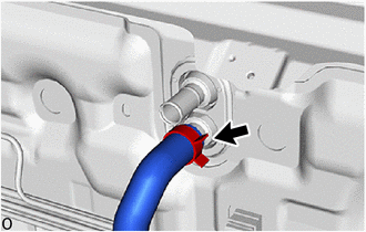
Using pliers, grip the claws of the clip and slide the clip to disconnect the inlet heater water hose.
- NOTICE:
- ·
Do not apply excessive force to the inlet heater water hose.
·Prepare a drain pan or cloth in case the coolant leaks.
87128
14.REMOVE HEATER GROMMET
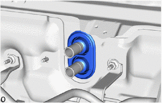
Remove the heater grommet.
15.REMOVE FRONT SEAT ASSEMBLY LH
16.REMOVE FRONT SEAT ASSEMBLY RH
- HINT:
-
Use the same procedure described for the LH side.
17.REMOVE INSTRUMENT PANEL SAFETY PAD ASSEMBLY
45250
18.REMOVE STEERING COLUMN ASSEMBLY
19.REMOVE TELEPHONE TRANSCEIVER WITH BRACKET
73233
20.REMOVE OUTER LAP BELT ANCHOR COVER
67918E
21.REMOVE REAR DOOR SCUFF PLATE LH
73220
22.REMOVE FRONT SEAT OUTER BELT ASSEMBLY LH
62414A
23.REMOVE LOWER CENTER PILLAR GARNISH LH
Remove the rear side of the front door opening trim weatherstrip LH so that the lower center pillar garnish LH can be removed.
Remove the front side of the rear door opening trim weatherstrip LH so that the lower center pillar garnish LH can be removed.
Remove the lower center pillar garnish LH.
67917C
24.REMOVE REAR DOOR SCUFF PLATE RH
- HINT:
-
Use the same procedure described as for the rear door scuff plate LH.
73210
25.REMOVE FRONT SEAT OUTER BELT ASSEMBLY RH
- HINT:
-
Use the same procedure described as for the front seat outer belt assembly LH.
62413A
26.REMOVE LOWER CENTER PILLAR GARNISH RH
- HINT:
-
Use the same procedure described as for the lower center pillar garnish LH.
78118
27.REMOVE ACCELERATOR PEDAL PAD
78010F
28.REMOVE ACCELERATOR PEDAL ASSEMBLY
58569D
29.REMOVE FRONT FLOOR CAUTION PLATE COVER
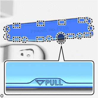

|
Place Finger Here |
Place your fingers at the positions shown in the illustration, detach the claw and guide and open the front floor caution plate cover.
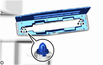
Detach the clip and remove the front floor caution plate cover.
58510C
30.REMOVE FRONT FLOOR FRONT CARPET ASSEMBLY
Remove the clip.
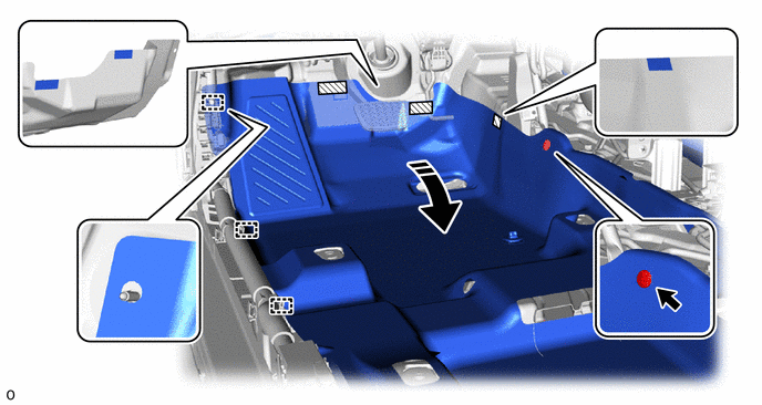
|
|
Fold Back | 
|
Fastener |
Detach the guide.
Detach each fastener and fold back the front floor front carpet assembly as shown in the illustration.
Remove the clip.
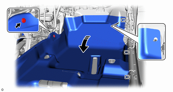
|
|
Fold Back | - | - |
Detach the guide and fold back the front floor front carpet assembly as shown in the illustration.
55215D
31.REMOVE NO. 3 DASH PANEL INSULATOR PAD
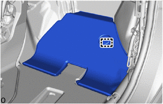
Detach the guide and remove the No. 3 dash panel insulator pad.
87216B
32.REMOVE REAR NO. 4 AIR DUCT
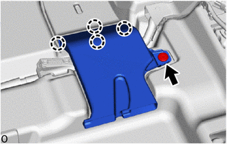
Remove the clip.
Detach the claw and remove the rear No. 4 air duct.
87213
33.REMOVE REAR NO. 2 AIR DUCT
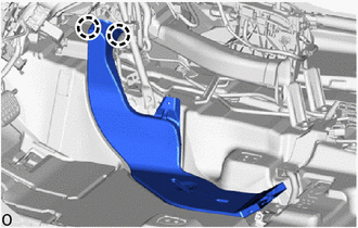
Detach the claw and remove the rear No. 2 air duct.
87215F
34.REMOVE REAR NO. 3 AIR DUCT
- HINT:
-
Use the same procedure as for the rear No. 4 air duct.
87212
35.REMOVE REAR NO. 1 AIR DUCT
- HINT:
-
Use the same procedure as for the rear No. 2 air duct.
58861B
36.REMOVE NO. 1 CONSOLE BOX DUCT
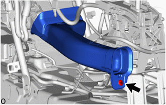
Remove the clip and No. 1 console box duct.
55085
37.REMOVE NO. 2 HEATER TO REGISTER DUCT SUB-ASSEMBLY
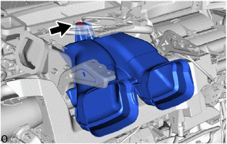
Remove the clip and No. 2 heater to register duct sub-assembly.
55308C
38.REMOVE CENTER INSTRUMENT PANEL BRACKET SUB-ASSEMBLY
39.REMOVE POWER DISTRIBUTION BOX ASSEMBLY WITH MAIN BODY ECU
40.DISCONNECT INSTRUMENT PANEL WIRE
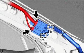
| *a | Clamp |
| *b | Guide |
Disconnect the 2 connectors.
Detach the clamp and guide.
Remove the 3 bolts.
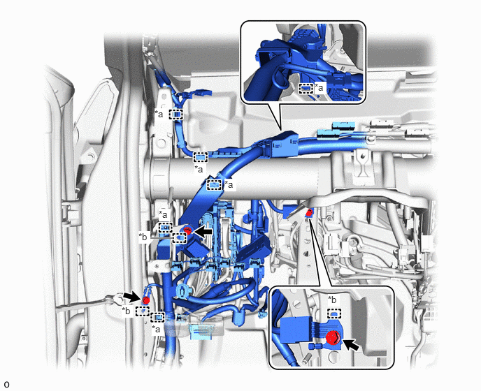
| *a | Clamp | *b | Guide |
Detach the guide and disconnect the 3 ground wires.
Detach the clamp.
Remove the nut.
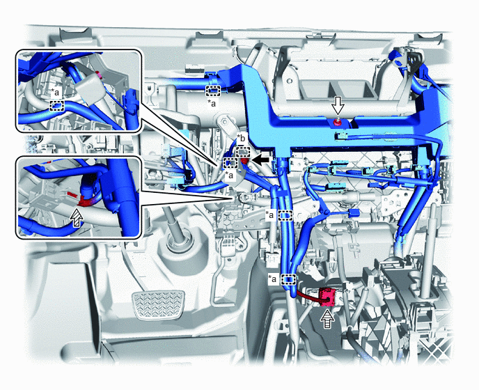
| *a | Clamp | *b | Guide |
|
|
Bolt |
|
Nut |

|
Connector | 
|
Lever Connector |
Remove the bolt.
Detach the guide and disconnect the ground wire.
Disconnect the connector.
Detach the clamp.
Disconnect the lever connector.
41.REMOVE DOOR CONTROL BATTERY
82877
42.REMOVE ECU INTEGRATION BOX RH
43.DISCONNECT INSTRUMENT PANEL WIRE
Remove the 2 bolts.
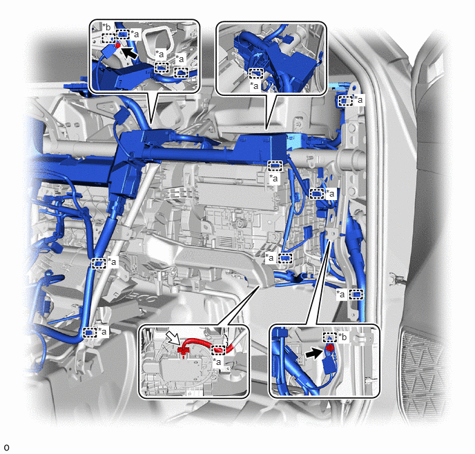
| *a | Clamp | *b | Guide |
|
|
Bolt |
|
Connector |
Detach the guide and disconnect the 2 ground wires.
Disconnect the connector.
Detach the clamp.
55306A
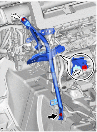
44.REMOVE NO. 1 INSTRUMENT PANEL BRACE SUB-ASSEMBLY
|
|
Bolt |
|
|
Nut |
|
|
Screw |
Remove the bolt, nut, screw and No. 1 instrument panel brace sub-assembly.
55307C
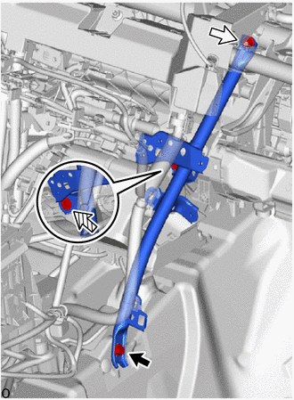
45.REMOVE NO. 2 INSTRUMENT PANEL BRACE SUB-ASSEMBLY
|
|
Bolt |
|
|
Nut |
|
|
Screw |
Remove the bolt, nut, screw and No. 2 instrument panel brace sub-assembly.
88539J
46.DISCONNECT DRAIN COOLER HOSE
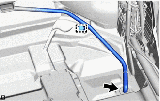
Detach the clamp.
Disconnect the drain cooler hose from the cooler unit drain hose grommet.
- NOTICE:
-
If the cooler unit drain hose grommet was removed from the body, replace it with a new one.
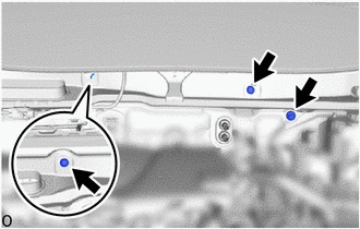
47.REMOVE INSTRUMENT PANEL REINFORCEMENT ASSEMBLY WITH AIR CONDITIONING UNIT ASSEMBLY
- NOTICE:
- ·
Be sure to support the air conditioning unit assembly when removing it because failure to do so may cause the bracket of the air conditioning unit assembly to break.
·When disassembling the air conditioning unit assembly, eliminate static electricity by touching the vehicle body to prevent the components from being damaged.
·Be careful not to damage the internal components of the instrument panel reinforcement assembly with air conditioning unit assembly on the glass etc. Only perform removal after first taking the appropriate actions.
·Do not allow the instrument panel reinforcement assembly with air conditioning unit assembly to strike the airbag ECU assembly. Doing so may damage the heater case, causing water leaks.
|
|
Bolt (A) |
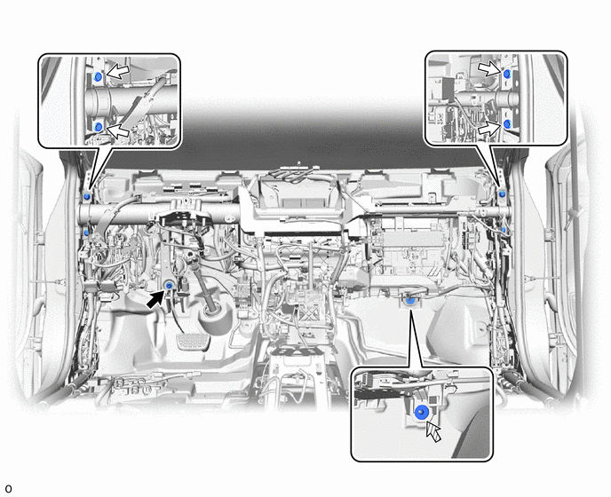
Remove the 3 bolts (A).
Remove the bolt (B).
|
|
Bolt (B) |
|
Bolt (C) |
|
|
Nut | - | - |
Remove the nut.
Remove the 4 bolts (C).
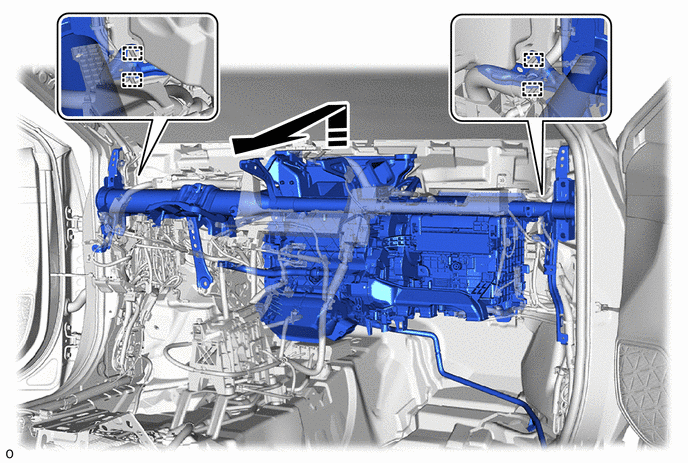
Remove the instrument panel reinforcement assembly with air conditioning unit assembly from the guide as shown in the illustration.
- NOTICE:
- When carrying the instrument panel reinforcement assembly with air conditioning unit assembly, hold the bottom of the assembly. Do not hold the following parts.
- ·
Do not hold the air conditioning harness assembly. Otherwise, static electricity from the technician may damage the air conditioning harness assembly.
·Do not hold the heater core or pipe of the heater radiator unit sub-assembly. Otherwise, the pipe may detach, the clamp may be damaged, or the crimped areas of the heater core and pipe of the heater radiator unit sub-assembly may be damaged, causing coolant to leak.
·Do not hold the air conditioning radiator damper servo sub-assembly, blower damper servo sub-assembly or link. Otherwise, the servo motor may become misaligned, causing abnormal operation noise, temperature control defects, or air leaks due to sealing defects in the doors.
·Do not hold the door. Doing so may cause air leaks due to closing defects resulting from excessive opening/closing. Also, keep the door free from oil and grease.
|
|
Remove in this Direction | - | - |
88650N
48.REMOVE AIR CONDITIONING AMPLIFIER ASSEMBLY
49.DISCONNECT INSTRUMENT PANEL WIRE
Disconnect the connector.
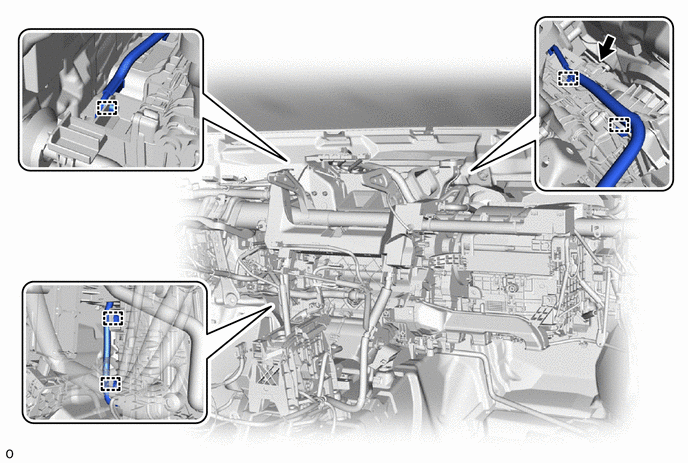
Detach the clamp.
50.REMOVE AIR CONDITIONING UNIT ASSEMBLY
- NOTICE:
- ·
Be sure to support the air conditioning unit assembly when removing it because failure to do so may cause the bracket of the air conditioning unit assembly to break.
·When disassembling the air conditioning unit assembly, eliminate static electricity by touching the vehicle body to prevent the components from being damaged.
·Be careful not to damage the internal components of the instrument panel reinforcement assembly and air conditioning unit assembly on the glass etc. Only perform removal after first taking the appropriate actions.
·Store the air conditioning unit assembly in a location free from sand and other foreign matter.
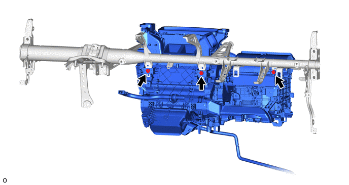
Remove the 3 bolts and air conditioning unit assembly from the instrument panel reinforcement assembly.
- NOTICE:
- When carrying the air conditioning unit assembly, hold the bottom of the assembly. Do not hold the following parts.
- ·
Do not hold the air conditioning harness assembly. Otherwise, static electricity from the technician may damage the air conditioning harness assembly.
·Do not hold the heater core or pipe of the heater radiator unit sub-assembly. Otherwise, the pipe may detach, the clamp may be damaged, or the crimped areas of the heater core and pipe of the heater radiator unit sub-assembly may be damaged, causing coolant to leak.
·Do not hold the air conditioning radiator damper servo sub-assembly, blower damper servo sub-assembly or link. Otherwise, the servo motor may become misaligned, causing abnormal operation noise, temperature control defects, or air leaks due to sealing defects in the doors.
·Do not hold the door. Doing so may cause air leaks due to closing defects resulting from excessive opening/closing. Also, keep the door free from oil and grease.
87201F
51.REMOVE NO. 3 AIR DUCT SUB-ASSEMBLY
- HINT:
-
Perform this procedure only when replacement of the No. 3 air duct sub-assembly is necessary.
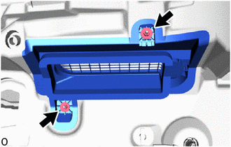
Remove the 2 nuts and No. 3 air duct sub-assembly.
88539G
52.REMOVE COOLER UNIT DRAIN HOSE GROMMET
- HINT:
-
Perform this procedure only when replacement of the cooler unit drain hose grommet is necessary.
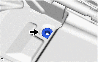
Remove the cooler unit drain hose grommet.
- NOTICE:
-
After removing the cooler unit drain hose grommet, replace it with a new one to prevent water from entering.