M20D-FKS FUEL FUEL INJECTOR(for Direct Injection) REMOVAL
CAUTION / NOTICE / HINT
The necessary procedures (adjustment, calibration, initialization or registration) that must be performed after parts are removed and installed, or replaced during direct fuel injector assembly removal/installation are shown below.
| Replaced Part or Performed Procedure | Necessary Procedure | Effect/Inoperative Function when Necessary Procedure not Performed | Link |
|---|---|---|---|
·
Replacement of direct fuel injector assembly ·
Replacement of throttle body with motor assembly ·
Cleaning the deposits from the throttle body with motor assembly ·
Replacement of EGR valve assembly ·
Gas leak from exhaust system is repaired |
Inspection after repair | ·
Poor idle, etc. ·
Engine start function, etc. |
( 202409,999999,_51,_083058,_0401834,RM100000002NA8M,) 202409,999999,_51,_083058,_0401834,RM100000002NA8M,)
|
- HINT:
-
When the cable is disconnected / reconnected to the auxiliary battery terminal, systems temporarily stop operating. However, each system has a function that completes learning the first time the system is used.
- ·
Learning completes when vehicle is driven
Effect/Inoperative when not Performed Necessary Procedures Link Stop and start system Drive the vehicle until stop and start control is permitted (approximately 5 to 60 minutes). ( 202409,999999,_51,_083056,_0402418,RM100000002NSFO,)
Lane tracing assist system Drive the vehicle straight ahead at 15 km/h (10 mph) or more for 1 second or more. ( 201910,999999,_58,_083101,_0401880,RM100000001JE9I,)
Pre-collision system
·Learning completes when vehicle is operated normally
Effect/Inoperative when not Performed Necessary Procedures Link *: w/ Power back door system
Power back door function* Fully close the back door by hand.
- HINT:
-
Initialization is not necessary if the above procedures are performed while the back door is closed.
( 202304,999999,_59,_083093,_0584672,RM1000000029PGT,)
Power door lock control system If the back door is locked and therefore cannot be opened, it is necessary to unlock the back door using the door control switch, electrical key transmitter sub-assembly switch. ( 202409,999999,_58,_083092,_0403003,RM100000002NS90,)
Air conditioning system After the ignition switch is turned to ON, the servo motor standard position is recognized -
- CAUTION:
- ·
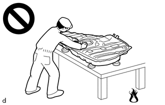
Never perform work on fuel system components near any possible ignition sources.
·Vaporized fuel could ignite, resulting in a serious accident.
- ·

Do not perform work on fuel system components without first disconnecting the cable from the negative (-) battery terminal.
·Sparks could cause vaporized fuel to ignite, resulting in a serious accident.
·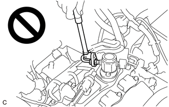
To prevent serious injury due to fuel spray from the high-pressure fuel lines, always discharge fuel system pressure before removing any fuel system components.
- NOTICE:
-
This procedure includes the removal of small-head bolts. Refer to Small-Head Bolts of Basic Repair Hint to identify the small-head bolts.
PROCEDURE

 1. DISCHARGE FUEL SYSTEM PRESSURE
2. PRECAUTION
- NOTICE:
-
After the ignition switch is turned off, there may be a waiting time before disconnecting the negative (-) battery terminal.
3.DISCONNECT CABLE FROM NEGATIVE BATTERY TERMINAL
17111
4.REMOVE INTAKE MANIFOLD
23801P
5.REMOVE NO. 1 FUEL PIPE SUB-ASSEMBLY
23814B
6.REMOVE FUEL DELIVERY PIPE
- NOTICE:
-
When replacing the fuel delivery pipe, it is necessary to replace the No. 1 fuel pipe sub-assembly with a new one.
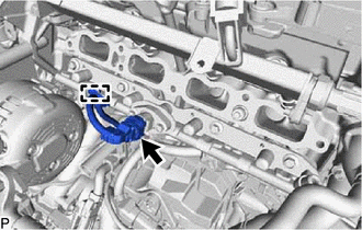
Detach the clamp and disconnect the connector from the fuel pressure sensor.
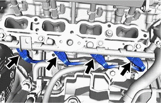
Disconnect the 4 connectors from the 4 direct fuel injector assemblies.
- NOTICE:
-
Make sure to disconnect the connectors carefully.
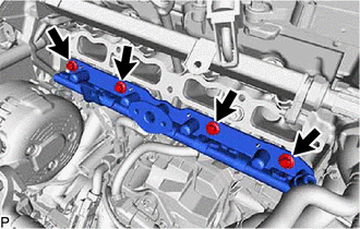
Remove the 4 bolts and fuel delivery pipe from the cylinder head sub-assembly.
- NOTICE:
- ·
Make sure not to touch or strike the tips of the direct fuel injector assemblies.
·Pull and remove the fuel delivery pipe in a straight line without tilting it.
23250E
7.REMOVE DIRECT FUEL INJECTOR ASSEMBLY
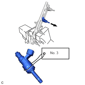
Secure the fuel delivery pipe in a vise between aluminum plates and pull out the 4 direct fuel injector assemblies.
- NOTICE:
- ·
Pull and remove each direct fuel injector assembly in a straight line to avoid damaging the seal surface of the fuel delivery pipe O-ring.
·After removing the direct fuel injector assemblies, remove any O-rings, No. 1 fuel injector back-up rings and No. 3 fuel injector back-up rings remaining on the fuel delivery pipe side.
·Attach a tag or label with the corresponding cylinder number to each direct fuel injector assembly so that they can be installed to their original locations.
·Cover the tip of each direct fuel injector assembly to prevent it from being damaged.
Remove the nozzle holder clamp from each direct fuel injector assembly.
Using needle nose pliers, remove the No. 3 fuel injector back-up ring from each direct fuel injector assembly.
- NOTICE:
-
Do not damage the area that contacts the O-ring.
Remove the O-ring and No. 1 fuel injector back-up ring from each direct fuel injector assembly.
Remove the C-ring and injector vibration insulator from each direct fuel injector assembly.
23255A
8.REMOVE FUEL INJECTOR SEAL
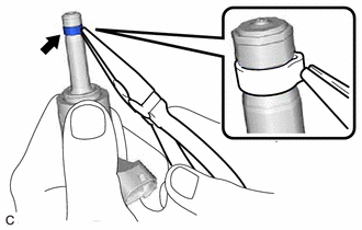
Using the tip of needle nose pliers, pinch and pull the fuel injector seal at several points to stretch it.
- NOTICE:
- ·
Excessively pinching the fuel injector seal may damage the groove of the direct fuel injector assembly.
·If a direct fuel injector assembly is dropped or the tip of the direct fuel injector assembly is struck, replace it with a new one.
Remove the fuel injector seal from each direct fuel injector assembly.