METER / GAUGE / DISPLAY METER / GAUGE SYSTEM(for SFTM Made) Fuel Receiver Gauge Display Malfunction
DESCRIPTION
The combination meter assembly uses the fuel sender gauge assembly and No. 2 fuel sender gauge assembly to detect the amount of fuel remaining in the fuel tank assembly. The Hall IC built into the fuel sender gauge assembly and No. 2 fuel sender gauge assembly changes the output voltage according to the amount of fuel remaining. The combination meter assembly receives fuel injection volume signals from the ECM and detects the voltage output from the fuel sender gauge assembly and No. 2 fuel sender gauge assembly and operates the fuel receiver gauge.
The combination meter assembly uses the fuel sender gauge assembly to detect the amount of fuel remaining in the fuel tank assembly. The Hall IC built into the fuel sender gauge assembly changes the output voltage according to the amount of fuel remaining. The combination meter assembly receives fuel injection volume signals from the ECM and detects the voltage output from the fuel sender gauge assembly and operates the fuel receiver gauge.
WIRING DIAGRAM
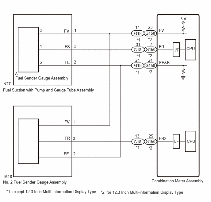
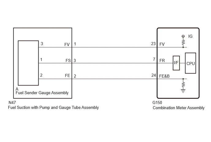
CAUTION / NOTICE / HINT
- CAUTION:
-
Be careful of flames.
- NOTICE:
-
When replacing the combination meter assembly, always replace it with a new one. If a combination meter assembly which was installed to another vehicle is used, the information stored in it will not match the information from the vehicle and a DTC may be stored.
PROCEDURE
Check if SFI system DTCs are output.
for A25F-FXS:
for M20D-FKS:
- Powertrain > Engine > Trouble Codes
- 50001 372
- Result:
Proceed to OK NG
OK
NG
for A25F-FXS:
for M20D-FKS:
Check vehicle condition.
- Result:
Result Proceed to except 12.3 Inch Multi-information Display Type A for 12.3 Inch Multi-information Display Type B
A
B
Using the GTS, perform the Active Test.
- Body Electrical > Combination Meter > Active Test
-
Tester Display Measurement Item Control Range Diagnostic Note Fuel Gauge Operation (Sender E) Fuel receiver gauge (Sender E) ON See [Display] Fuel Gauge Operation (Empty) Fuel receiver gauge (Empty) ON See [Display] Fuel Gauge Operation (Warning) Fuel receiver gauge (Warning) ON See [Display] Fuel Gauge Operation (1/4) Fuel receiver gauge (1/4) ON See [Display] Fuel Gauge Operation (1/2) Fuel receiver gauge (1/2) ON See [Display] Fuel Gauge Operation (3/4) Fuel receiver gauge (3/4) ON See [Display] Fuel Gauge Operation (Full) Fuel receiver gauge (Full) ON See [Display] Fuel Gauge Operation (Sender F) Fuel receiver gauge (Sender F) ON See [Display]
- Body Electrical > Combination Meter > Active Test
-
Tester Display Fuel Gauge Operation (Sender E) - 50004 409 221
- Body Electrical > Combination Meter > Active Test
-
Tester Display Fuel Gauge Operation (Empty) - 50004 409 222
- Body Electrical > Combination Meter > Active Test
-
Tester Display Fuel Gauge Operation (Warning) - 50004 409 223
- Body Electrical > Combination Meter > Active Test
-
Tester Display Fuel Gauge Operation (1/4) - 50004 409 224
- Body Electrical > Combination Meter > Active Test
-
Tester Display Fuel Gauge Operation (1/2) - 50004 409 225
- Body Electrical > Combination Meter > Active Test
-
Tester Display Fuel Gauge Operation (3/4) - 50004 409 226
- Body Electrical > Combination Meter > Active Test
-
Tester Display Fuel Gauge Operation (Full) - 50004 409 227
- Body Electrical > Combination Meter > Active Test
-
Tester Display Fuel Gauge Operation (Sender F) - 50004 409 228
- OK:
Fuel receiver gauge indication is normal.
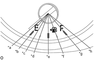
| *a | Fuel Gauge Operation (Sender E) |
| *b | Fuel Gauge Operation (Empty) |
| *c | Fuel Gauge Operation (Warning) |
| *d | Fuel Gauge Operation (1/4) |
| *e | Fuel Gauge Operation (1/2) |
| *f | Fuel Gauge Operation (3/4) |
| *g | Fuel Gauge Operation (Full) |
| *h | Fuel Gauge Operation (Sender F) |
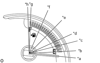
| *a | Fuel Gauge Operation (Sender E) |
| *b | Fuel Gauge Operation (Empty) |
| *c | Fuel Gauge Operation (Warning) |
| *d | Fuel Gauge Operation (1/4) |
| *e | Fuel Gauge Operation (1/2) |
| *f | Fuel Gauge Operation (3/4) |
| *g | Fuel Gauge Operation (Full) |
| *h | Fuel Gauge Operation (Sender F) |
[Display]: Fuel receiver gauge
- Result:
Result Proceed to OK (for Gasoline Model) A OK (for HV Model) B NG C
A
B
C
*1: except 12.3 Inch Multi-information Display Type
*2: for 12.3 Inch Multi-information Display Type
Disconnect the G18*1 or G150*2 combination meter assembly connector.
Disconnect the N27 fuel suction with pump and gauge tube assembly connector.
Disconnect the M18 No. 2 fuel sender gauge assembly connector.
Measure the resistance according to the value(s) in the table below.
- Standard Resistance:
except 12.3 Inch Multi-information Display Type Tester Connection Condition Specified Condition N27-3 (FS) - G18-31 (FR) Always Below 1 Ω N27-2 (FE) - G18-24 (FE&B) Always Below 1 Ω N27-1 (FV) - G18-14 (FV) Always Below 1 Ω M18-3 (FR) - G18-13 (FR2) Always Below 1 Ω M18-2 (FE) - G18-24 (FE&B) Always Below 1 Ω M18-1 (FV) - G18-14 (FV) Always Below 1 Ω N27-3 (FS) or G18-31 (FR) - Other terminals and body ground Always 10 kΩ or higher N27-2 (FE) or G18-24 (FE&B) - Other terminals and body ground Always 10 kΩ or higher N27-1 (FV) or G18-14 (FV) - Other terminals and body ground Always 10 kΩ or higher M18-3 (FR) or G18-13 (FR2) - Other terminals and body ground Always 10 kΩ or higher M18-2 (FE) or G18-24 (FE&B) - Other terminals and body ground Always 10 kΩ or higher M18-1 (FV) or G18-14 (FV) - Other terminals and body ground Always 10 kΩ or higher
for 12.3 Inch Multi-information Display Type Tester Connection Condition Specified Condition N27-3 (FS) - G150-7 (FR) Always Below 1 Ω N27-2 (FE) - G150-24 (FE&B) Always Below 1 Ω N27-1 (FV) - G150-23 (FV) Always Below 1 Ω M18-3 (FR) - G150-25 (FR2) Always Below 1 Ω M18-2 (FE) - G150-24 (FE&B) Always Below 1 Ω M18-1 (FV) - G150-23 (FV) Always Below 1 Ω N27-3 (FS) or G150-7 (FR) - Other terminals and body ground Always 10 kΩ or higher N27-2 (FE) or G150-24 (FE&B) - Other terminals and body ground Always 10 kΩ or higher N27-1 (FV) or G150-23 (FV) - Other terminals and body ground Always 10 kΩ or higher M18-3 (FR) or G150-25 (FR2) - Other terminals and body ground Always 10 kΩ or higher M18-2 (FE) or G150-24 (FE&B) - Other terminals and body ground Always 10 kΩ or higher M18-1 (FV) or G150-23 (FV) - Other terminals and body ground Always 10 kΩ or higher
- Result:
Proceed to OK NG
OK
NG
Remove the fuel sender gauge assembly.
Inspect the fuel sender gauge assembly.
- Result:
Proceed to OK NG
OK
NG
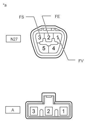
| *a | Component without harness connected
(Fuel Suction with Pump and Gauge Tube Assembly) |
Measure the resistance according to the value(s) in the table below.
- Standard Resistance:
Tester Connection Condition Specified Condition N27-1 (FV) - A-3 Always Below 1 Ω N27-2 (FE) - A-2 Always Below 1 Ω N27-3 (FS) - A-1 Always Below 1 Ω
- Result:
Proceed to OK NG
OK
NG
Remove the No. 2 fuel sender gauge assembly.
Inspect the No. 2 fuel sender gauge assembly.
- Result:
Proceed to OK NG
OK
NG
Disconnect the N47 fuel suction with pump and gauge tube assembly connector.
Disconnect the G150 combination meter assembly connector.
Measure the resistance according to the value(s) in the table below.
- Standard Resistance:
Tester Connection Condition Specified Condition N47-3 (FS) - G150-7 (FR) Always Below 1 Ω N47-2 (FE) - G150-24 (FE&B) Always Below 1 Ω N47-1 (FV) - G150-23 (FV) Always Below 1 Ω N47-3 (FS) or G150-7 (FR) - Other terminals and body ground Always 10 kΩ or higher N47-2 (FE) or G150-24 (FE&B) - Other terminals and body ground Always 10 kΩ or higher N47-1 (FV) or G150-23 (FV) - Other terminals and body ground Always 10 kΩ or higher
- Result:
Proceed to OK NG
OK
NG
Inspect the fuel sender gauge assembly.
- Result:
Proceed to OK NG
OK
NG
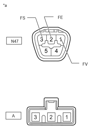
| *a | Component without harness connected
(Fuel Suction with Pump and Gauge Tube Assembly) |
Measure the resistance according to the value(s) in the table below.
- Standard Resistance:
Tester Connection Condition Specified Condition N47-1 (FV) - A-3 Always Below 1 Ω N47-2 (FE) - A-2 Always Below 1 Ω N47-3 (FS) - A-1 Always Below 1 Ω
- Result:
Proceed to OK NG
OK
NG
Using the Techstream, read the Data List.
- Body Electrical > Combination Meter > Data List
-
Tester Display Measurement Item Range Normal Condition Diagnostic Note Fuel Input Fuel input Min.: 0 L, Max.: 655.35 L or Unset for Gasoline Model:·Fuel receiver gauge indicates F: 47.13 L
·Fuel receiver gauge indicates 3/4: 37.66 L
·Fuel receiver gauge indicates 1/2: 28.18 to 27.11 L
·Fuel receiver gauge indicates 1/4: 13.75 L
·Fuel receiver gauge indicates E: 5.71 L
for HV Model:·Fuel receiver gauge indicates F: 47.66 L
·Fuel receiver gauge indicates 3/4: 37.58 L
·Fuel receiver gauge indicates 1/2: 27.5 L
·Fuel receiver gauge indicates 1/4: 13.75 L
·Fuel receiver gauge indicates E: 5.50 L
- Sub Fuel Input Sub fuel input Min.: 0 L, Max.: 655.35 L or Unset ·Fuel receiver gauge indicates F: 47.13 L
·Fuel receiver gauge indicates 3/4: 37.66 L
·Fuel receiver gauge indicates 1/2: 28.18 L
·Fuel receiver gauge indicates 1/4: 0.00 L
·Fuel receiver gauge indicates E: 0.00 L
for Gasoline Model
- Body Electrical > Combination Meter > Data List
-
Tester Display Fuel Input Sub Fuel Input - 50003 409 20,21
- OK:
Fuel level displayed on the Techstream is almost the same as the fuel receiver gauge indication.
- Result:
Result Proceed to OK (for Gasoline Model) A OK (for HV Model) B NG C
A
B
C