METER / GAUGE / DISPLAY METER / GAUGE SYSTEM(for SFTM Made) B132187 Lost Communication with EMV Missing Message
DESCRIPTION
*1: w/o Navigation System
*2: w/ Navigation System
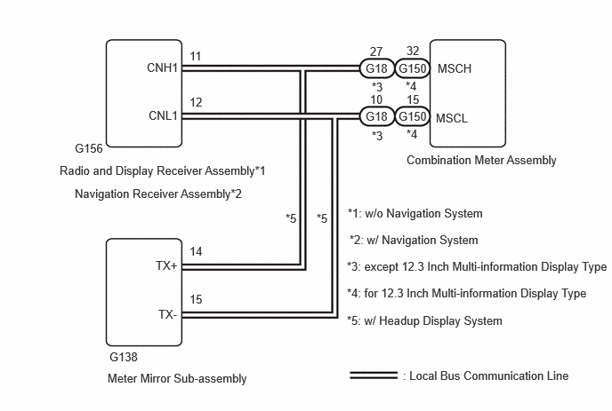
The combination meter assembly, meter mirror sub-assembly and radio and display receiver assembly*1 or navigation receiver assembly*2 communicate via local bus communication. This allows audio and visual system information to be displayed on the multi-information display. This DTC is stored when a communication error occurs between the radio and display receiver assembly and combination meter assembly.
| DTC No. | Detection Item | DTC Detection Condition | Trouble Area |
|---|---|---|---|
| B132187 | Lost Communication with EMV Missing Message | Diagnosis Condition:
·
Ignition switch ON ·
IG power source voltage is 9.5 V or more Malfunction Status: No communication with radio and display receiver assembly (w/o Navigation System) or navigation receiver assembly (w/ Navigation System) Malfunction Time: 3.0 seconds or more |
·
Harness or connector ·
Navigation receiver assembly (w/ Navigation System) ·
Radio and display receiver assembly (w/o Navigation System) ·
Meter mirror sub-assembly (w/ Headup Display System) ·
Combination meter mirror ECU |
| Pattern | DTC Output Part Name
(Display on GTS) |
Suspected Area (Malfunction Status) | ||
|---|---|---|---|---|
| Combination Meter Assembly
(Combination Meter) |
Navigation Receiver Assembly
(Navigation System) |
Meter Mirror Sub-assembly
(Head Up Display) |
||
| B132187 | U11D087 | B132187 | ||
|
○: DTC is output. -: DTC is not output |
||||
| Pattern 1 | ○ | ○ | ○ | Local bus (Open or short) |
| Meter mirror sub-assembly (Internal malfunction) | ||||
| Navigation receiver assembly (Internal malfunction) | ||||
| Combination meter assembly (Internal malfunction) | ||||
| Pattern 2 | ○ | ○ | - | Local bus (Open) |
| Combination meter assembly (Internal malfunction) | ||||
| Pattern 3 | ○ | - | ○ | Navigation receiver assembly (Internal malfunction) |
| Pattern 4 | ○ | - | - | Combination meter assembly (Internal malfunction) |
| Pattern | DTC Output Part Name
(Display on GTS) |
Suspected Area (Malfunction Status) | |
|---|---|---|---|
| Combination Meter Assembly
(Combination Meter) |
Radio and Display Receiver Assembly*1
Navigation Receiver Assembly*2 (Navigation System) |
||
| B132187 | U11D087 | ||
|
○: DTC is output. -: DTC is not output |
|||
| Pattern 1 | ○ | ○ | Local bus (Open or short) |
| Radio and display receiver assembly (Internal malfunction)*1 | |||
| Navigation receiver assembly (Internal malfunction)*2 | |||
| Combination meter assembly (Internal malfunction) | |||
| Pattern 2 | ○ | - | Local bus branch line (Open) |
| Radio and display receiver assembly (Internal malfunction)*1 | |||
| Radio and display receiver assembly (Internal malfunction)*1 | |||
| Combination meter assembly (Internal malfunction) | |||
WIRING DIAGRAM
CAUTION / NOTICE / HINT
- NOTICE:
- ·
When replacing the combination meter assembly, always replace it with a new one. If a combination meter assembly which was installed to another vehicle is used, the information stored in it will not match the information from the vehicle and a DTC may be stored.
·After the ignition switch is turned off, there may be a waiting time before disconnecting the negative (-) auxiliary battery terminal.
·When disconnecting and reconnecting the auxiliary battery
- HINT:
-
When disconnecting and reconnecting the auxiliary battery, there is an automatic learning function that completes learning when the respective system is used.
PROCEDURE
Check vehicle condition.
- Result:
Result Proceed to w/ Headup Display System A w/o Headup Display System B
A
B
Check for DTCs and output pattern according to the following table.
- Body Electrical > Head Up Display > Trouble Codes
- 50001 408
- Body Electrical > Combination Meter > Trouble Codes
- 50001 409
- Body Electrical > Navigation System > Trouble Codes
- 50001 496
| Pattern | DTC Output Part Name
(Display on GTS) |
||
|---|---|---|---|
| Combination Meter Assembly
(Combination Meter) |
Navigation Receiver Assembly
(Navigation System) |
Meter Mirror Sub-assembly
(Head Up Display) |
|
| B132187 | U11D087 | B132187 | |
|
○: DTC is output. -: DTC is not output |
|||
| Pattern 1 | ○ | ○ | ○ |
| Pattern 2 | ○ | ○ | - |
| Pattern 3 | ○ | - | ○ |
| Pattern 4 | ○ | - | - |
- Result:
Result Proceed to Pattern 1 A Pattern 2 B Pattern 3 C Pattern 4 D
A
B
C
D
Disconnect the G138 meter mirror sub-assembly connector.
Clear the DTCs.
- Body Electrical > Combination Meter > Clear DTCs
- 50002 409
Check for DTCs.
- Body Electrical > Combination Meter > Trouble Codes
- 50001 409
- Result:
Result Proceed to DTC B132187 is output. A DTC B132187 is not output. B
A
B
Disconnect the cable from the negative (-) auxiliary battery terminal.
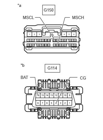
| *a | Front view of wire harness connector
(to Combination Meter Assembly) |
| *b | Front view of wire harness connector
(DLC3) |
Disconnect the combination meter assembly connector.
Measure the resistance according to the value(s) in the table below.
- Standard Resistance:
Tester Connection Condition Specified Condition G150-32 (MSCH) - G150-15 (MSCL) Cable disconnected from negative (-) auxiliary battery terminal 108 to 132 Ω G150-32 (MSCH) - G114-4 (CG) Cable disconnected from negative (-) auxiliary battery terminal 200 Ω or higher G150-15 (MSCL) - G114-4 (CG) Cable disconnected from negative (-) auxiliary battery terminal 200 Ω or higher G150-32 (MSCH) - G114-16 (BAT) Cable disconnected from negative (-) auxiliary battery terminal 6 kΩ or higher G150-15 (MSCL) - G114-16 (BAT) Cable disconnected from negative (-) auxiliary battery terminal 6 kΩ or higher
- Result:
Proceed to OK NG
OK
NG
Disconnect the cable from the negative (-) auxiliary battery terminal.
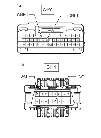
| *a | Front view of wire harness connector
(to Navigation Receiver Assembly) |
| *b | Front view of wire harness connector
(DLC3) |
Disconnect the navigation receiver assembly connector.
Measure the resistance according to the value(s) in the table below.
- Standard Resistance:
Tester Connection Condition Specified Condition G156-11 (CNH1) - G156-12 (CNL1) Cable disconnected from negative (-) auxiliary battery terminal 108 to 132 Ω G156-11 (CNH1) - G114-4 (CG) Cable disconnected from negative (-) auxiliary battery terminal 200 Ω or higher G156-12 (CNL1) - G114-4 (CG) Cable disconnected from negative (-) auxiliary battery terminal 200 Ω or higher G156-11 (CNH1) - G114-16 (BAT) Cable disconnected from negative (-) auxiliary battery terminal 6 kΩ or higher G156-12 (CNL1) - G114-16 (BAT) Cable disconnected from negative (-) auxiliary battery terminal 6 kΩ or higher
- Result:
Proceed to OK NG
OK
NG
Disconnect the cable from the negative (-) auxiliary battery terminal.
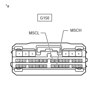
| *a | Front view of wire harness connector
(to Combination Meter Assembly) |
Disconnect the combination meter assembly connector.
Measure the resistance according to the value(s) in the table below.
- Standard Resistance:
Tester Connection Condition Specified Condition G150-32 (MSCH) - G150-15 (MSCL) Cable disconnected from negative (-) auxiliary battery terminal 108 to 132 Ω
- Result:
Proceed to OK NG
OK
NG
Check for DTCs and output pattern according to the following table.
- Body Electrical > Combination Meter > Trouble Codes
- 50001 409
- Body Electrical > Navigation System > Trouble Codes
- 50001 496
| Pattern | DTC Output Part Name
(Display on GTS) |
|
|---|---|---|
| Combination Meter Assembly
(Combination Meter) |
Radio and Display Receiver Assembly (w/o Navigation System)
Navigation Receiver Assembly (w/ Navigation System) (Navigation System) |
|
| B132187 | U11D087 | |
|
○: DTC is output. -: DTC is not output |
||
| Pattern 1 | ○ | ○ |
| Pattern 2 | ○ | - |
- Result:
Result Proceed to Pattern 1 A Pattern 2 B
A
B
Check vehicle condition.
- Result:
Result Proceed to except 12.3 Inch Multi-information Display Type A for 12.3 Inch Multi-information Display Type B
A
B
Disconnect the cable from the negative (-) auxiliary battery terminal.
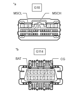
| *a | Front view of wire harness connector
(to Combination Meter Assembly) |
| *b | Front view of wire harness connector
(DLC3) |
Disconnect the combination meter assembly connector.
Measure the resistance according to the value(s) in the table below.
- Standard Resistance:
Tester Connection Condition Specified Condition G18-27 (MSCH) - G18-10 (MSCL) Cable disconnected from negative (-) auxiliary battery terminal 108 to 132 Ω G18-27 (MSCH) - G114-4 (CG) Cable disconnected from negative (-) auxiliary battery terminal 200 Ω or higher G18-10 (MSCL) - G114-4 (CG) Cable disconnected from negative (-) auxiliary battery terminal 200 Ω or higher G18-27 (MSCH) - G114-16 (BAT) Cable disconnected from negative (-) auxiliary battery terminal 6 kΩ or higher G18-10 (MSCL) - G114-16 (BAT) Cable disconnected from negative (-) auxiliary battery terminal 6 kΩ or higher
- Result:
Result Proceed to OK A NG (w/o Navigation System) B NG (w/ Navigation System) C
A
B
C
Disconnect the cable from the negative (-) auxiliary battery terminal.
| *a | Front view of wire harness connector
(to Radio and Display Receiver Assembly) |
| *b | Front view of wire harness connector
(DLC3) |
Disconnect the radio and display receiver assembly connector.
Measure the resistance according to the value(s) in the table below.
- Standard Resistance:
Tester Connection Condition Specified Condition G156-11 (CNH1) - G156-12 (CNL1) Cable disconnected from negative (-) auxiliary battery terminal 108 to 132 Ω G156-11 (CNH1) - G114-4 (CG) Cable disconnected from negative (-) auxiliary battery terminal 200 Ω or higher G156-12 (CNL1) - G114-4 (CG) Cable disconnected from negative (-) auxiliary battery terminal 200 Ω or higher G156-11 (CNH1) - G114-16 (BAT) Cable disconnected from negative (-) auxiliary battery terminal 6 kΩ or higher G156-12 (CNL1) - G114-16 (BAT) Cable disconnected from negative (-) auxiliary battery terminal 6 kΩ or higher
- Result:
Proceed to OK NG
OK
NG
Disconnect the cable from the negative (-) auxiliary battery terminal.
| *a | Front view of wire harness connector
(to Navigation Receiver Assembly) |
| *b | Front view of wire harness connector
(DLC3) |
Disconnect the navigation receiver assembly connector.
Measure the resistance according to the value(s) in the table below.
- Standard Resistance:
Tester Connection Condition Specified Condition G156-11 (CNH1) - G156-12 (CNL1) Cable disconnected from negative (-) auxiliary battery terminal 108 to 132 Ω G156-11 (CNH1) - G114-4 (CG) Cable disconnected from negative (-) auxiliary battery terminal 200 Ω or higher G156-12 (CNL1) - G114-4 (CG) Cable disconnected from negative (-) auxiliary battery terminal 200 Ω or higher G156-11 (CNH1) - G114-16 (BAT) Cable disconnected from negative (-) auxiliary battery terminal 6 kΩ or higher G156-12 (CNL1) - G114-16 (BAT) Cable disconnected from negative (-) auxiliary battery terminal 6 kΩ or higher
- Result:
Proceed to OK NG
OK
NG
Disconnect the cable from the negative (-) auxiliary battery terminal.
| *a | Front view of wire harness connector
(to Combination Meter Assembly) |
| *b | Front view of wire harness connector
(DLC3) |
Disconnect the combination meter assembly connector.
Measure the resistance according to the value(s) in the table below.
- Standard Resistance:
Tester Connection Condition Specified Condition G150-32 (MSCH) - G150-15 (MSCL) Cable disconnected from negative (-) auxiliary battery terminal 108 to 132 Ω G150-32 (MSCH) - G114-4 (CG) Cable disconnected from negative (-) auxiliary battery terminal 200 Ω or higher G150-15 (MSCL) - G114-4 (CG) Cable disconnected from negative (-) auxiliary battery terminal 200 Ω or higher G150-32 (MSCH) - G114-16 (BAT) Cable disconnected from negative (-) auxiliary battery terminal 6 kΩ or higher G150-15 (MSCL) - G114-16 (BAT) Cable disconnected from negative (-) auxiliary battery terminal 6 kΩ or higher
- Result:
Result Proceed to OK A NG (w/o Navigation System) B NG (w/ Navigation System) C
A
B
C
Check vehicle condition.
- Result:
Result Proceed to w/o Navigation System A w/ Navigation System B
A
B
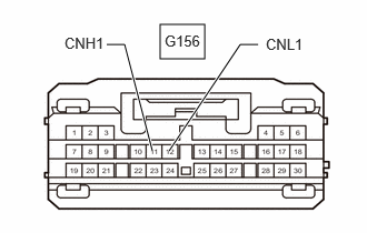
| *a | Front view of wire harness connector
(to Radio and Display Receiver Assembly) |
Disconnect the radio and display receiver assembly connector.
Measure the resistance according to the value(s) in the table below.
- Standard Resistance:
Tester Connection Switch Condition Tool Setting Specified Condition G156-11 (CNH1) - G156-12 (CNL1) Ignition switch ON 1 V/DIV., 100 μs./DIV. Pulse generation
- Result:
Proceed to OK NG
OK
NG
| *a | Front view of wire harness connector
(to Navigation Receiver Assembly) |
Disconnect the navigation receiver assembly connector.
Measure the resistance according to the value(s) in the table below.
- Standard Resistance:
Tester Connection Switch Condition Tool Setting Specified Condition G156-11 (CNH1) - G156-12 (CNL1) Ignition switch ON 1 V/DIV., 100 μs./DIV. Pulse generation
- Result:
Proceed to OK NG
OK
NG