RM36D0EC
_56
Audio / Visual / Telematics
_083087
TELEMATICS
_0402655
TELEMATICS SYSTEM
J
TELEMATICS TELEMATICS SYSTEM Received Voice Signal Circuit
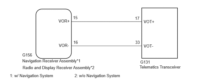
WIRING DIAGRAM
2.458,0.51 3.073,0.708
0.615,0.198
10
false
15
1.969,0.625 2.583,0.823
0.615,0.198
10
false
VOR+
1.979,1.448 2.594,1.646
0.615,0.198
10
false
VOR-
4.833,0.646 5.448,0.844
0.615,0.198
10
false
VOT+
4.833,1.469 5.448,1.667
0.615,0.198
10
false
VOT-
0.75,1.771 1.365,1.969
0.615,0.198
10
false
G156
0.75,1.969 2.781,2.26
2.031,0.292
10
false
Navigation Receiver Assembly*1
2.469,1.344 2.76,1.542
0.292,0.198
10
false
16
4.552,1.344 4.844,1.542
0.292,0.198
10
false
33
4.542,0.531 4.833,0.729
0.292,0.198
10
false
17
4.719,2.01 5.333,2.208
0.615,0.198
10
false
G131
4.698,2.177 6.271,2.396
1.573,0.219
10
false
Telematics Transceiver
0.76,2.198 3.448,2.427
2.688,0.229
10
false
Radio and Display Receiver Assembly*2
0.333,2.469 3.021,2.698
2.688,0.229
10
false
1: w/ Navigation System
2.51,2.469 5.198,2.698
2.688,0.229
10
false
2: w/o Navigation System
CAUTION / NOTICE / HINT
- NOTICE:
- ·
Depending on the parts that are replaced during vehicle inspection or maintenance, performing initialization, registration or calibration may be needed. Refer to Precaution for Telematics System.
·Before replacing the telematics transceiver, refer to Service Bulletin.
PROCEDURE
1.CHECK HARNESS AND CONNECTOR (NAVIGATION RECEIVER ASSEMBLY OR RADIO AND DISPLAY RECEIVER ASSEMBLY - TELEMATICS TRANSCEIVER)
*1: w/ Navigation System
*2: w/o Navigation System
a.
Disconnect the G156 navigation receiver assembly*1, radio and display receiver assembly*2 connector.
b.
Disconnect the G131 telematics transceiver connector.
c.
Measure the resistance according to the value(s) in the table below.
- Standard Resistance:
Tester Connection Condition Specified Condition G156-15 (VOR+) - G131-17 (VOT+) Always Below 1 Ω G156-16 (VOR-) - G131-33 (VOT-) Always Below 1 Ω G156-15 (VOR+) - Body ground Always 10 kΩ or higher G156-16 (VOR-) - Body ground Always 10 kΩ or higher
- Result:
Proceed to OK NG
OK
2.CHECK TELEMATICS TRANSCEIVER
NG
REPAIR OR REPLACE HARNESS OR CONNECTOR
2.CHECK TELEMATICS TRANSCEIVER
a.
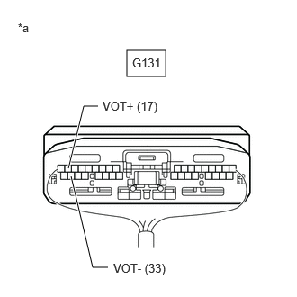
Remove the telematics transceiver with the connectors still connected.
b.
1.469,0.583 1.917,0.885
0.448,0.302
0.823,2.042 1.073,3.094
1.073,3.094 1.25,3.094
true
0.792,1.948 0.969,1.229
0.969,1.229 1.135,1.229
true
1.188,1.146 2.052,1.427
0.865,0.281
10
false
VOT+ (17)
1.313,3.021 1.958,3.271
0.646,0.25
10
false
VOT- (33)
0.208,0.24 0.458,0.427
0.25,0.188
10
false
*a
1.531,0.646 2.167,1.01
0.635,0.365
10
false
G131
| *a | Component with harness connected
(Telematics Transceiver) |
Check for pulses according to the value(s) in the table below.
- Standard:
Tester Connection Condition Specified Condition G131-17 (VOT+) - Body ground Calling while using the operator service A waveform synchronized with the sent voice is output G131-33 (VOT-) - Body ground Calling while using the operator service A waveform synchronized with the sent voice is output
- Result:
Result Proceed to OK (w/ Navigation System) A OK (w/o Navigation System) B NG C
A
REPLACE NAVIGATION RECEIVER ASSEMBLY
B
REPLACE RADIO AND DISPLAY RECEIVER ASSEMBLY
C
3.REPLACE TELEMATICS TRANSCEIVER
3.REPLACE TELEMATICS TRANSCEIVER
a.
Replace the telematics transceiver with a new one.
- Result:
Proceed to NEXT
NEXT
PERFORM REGISTRATION