TELEMATICS TELEMATICS TRANSCEIVER REMOVAL
CAUTION / NOTICE / HINT
The necessary procedures (adjustment, calibration, initialization or registration) that must be performed after parts are removed, installed or replaced during the telephone transceiver removal/installation are shown below.
| Replacement Part or Procedure | Necessary Procedures | Effect/Inoperative Function When Necessary Procedures are not Performed | Link |
|---|---|---|---|
| Telephone transceiver | ·
Register vehicle information ·
DCM activation |
·
Emergency call service ·
Telematics service |
( 202304,999999,_56,_083087,_0402655,RM1000000029YMH,) 202304,999999,_56,_083087,_0402655,RM1000000029YMH,)
|
| Code registration | Telematics system | See Service Bulletin for the registration method. |
| Replacement Part or Procedure | Necessary Procedures | Effect/Inoperative Function When Necessary Procedures are not Performed | Link |
|---|---|---|---|
| Telephone transceiver | ·
Register vehicle information ·
DCM activation |
·
Emergency call service ·
Telematics service |
(202304,999999,_56,_083087,_0402655,RM1000000029YMH,)
|
w/ Smart Entry and Start System:
·
Telephone transceiver |
Code registration | Telematics system | See Service Bulletin for the registration method. |
PROCEDURE

 33504F
1.REMOVE SHIFT LEVER KNOB SUB-ASSEMBLY
33504F
1.REMOVE SHIFT LEVER KNOB SUB-ASSEMBLY
for Gasoline Model:
58804A
2.REMOVE UPPER CONSOLE PANEL SUB-ASSEMBLY
58813
3.REMOVE UPPER CONSOLE BOX (w/o Wireless Charger)
861C0
4.REMOVE MOBILE WIRELESS CHARGER CRADLE ASSEMBLY (w/ Wireless Charger)
58805C
5.REMOVE REAR UPPER CONSOLE PANEL SUB-ASSEMBLY
55900
6.REMOVE AIR CONDITIONING CONTROL ASSEMBLY
55434B
7.REMOVE LOWER CENTER INSTRUMENT PANEL FINISH PANEL
8.REMOVE TELEPHONE TRANSCEIVER WITH BRACKET
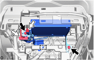

|
Bolt |

|
Connector |
Remove the 2 bolts.
Disconnect the 2 connectors and detach the clamp.
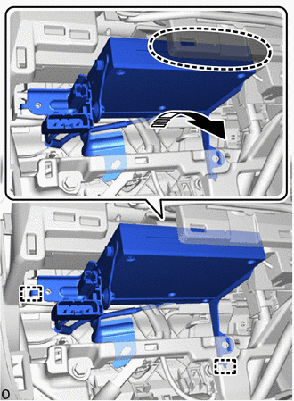

|
Place Hand Here |

|
Remove in this Direction |
Place your hand at the position shown in the illustration, and then while bending the instrument panel safety pad assembly, detach the guide and remove the telephone transceiver with bracket.
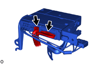
Disconnect the 2 connectors.
- HINT:
-
Remove the telephone transceiver with bracket together with the No. 4 antenna cord sub-assembly and telephone ECU wire (to transceiver).
86713A
9.REMOVE TELEPHONE ECU WIRE (TO TRANSCEIVER)
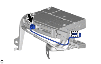
Disconnect the connector.
Detach the clamp and remove the telephone ECU wire (to transceiver).
86101Q
10.REMOVE NO. 4 ANTENNA CORD SUB-ASSEMBLY
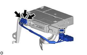
Disconnect the 3 connectors.
Detach the clamp and remove the No. 4 antenna cord sub-assembly.
86719A
11.REMOVE NO. 1 TELEPHONE BRACKET
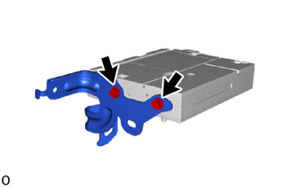
Remove the 2 screws and No. 1 telephone bracket.
86719B
12.REMOVE NO. 2 TELEPHONE BRACKET
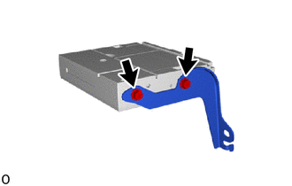
Remove the 2 screws and No. 2 telephone bracket.
86741A
13.REMOVE TELEPHONE TRANSCEIVER