DOOR / HATCH POWER BACK DOOR SYSTEM Jam Protection Function Activates During Power Back Door Operation
DESCRIPTION
The power back door is controlled by the multiplex network door ECU and the back door motor is driven. During motor operation, the power back door (touch sensor) used for jam protection checks for obstruction by foreign objects, etc. by detecting changes in resistance due to contact.
Furthermore, the speed of the back door is monitored using the pulse sensor (power back door unit assembly) and if a change in speed is detected, it is judged that there is an obstruction by a foreign object and the door direction is reversed.
WIRING DIAGRAM
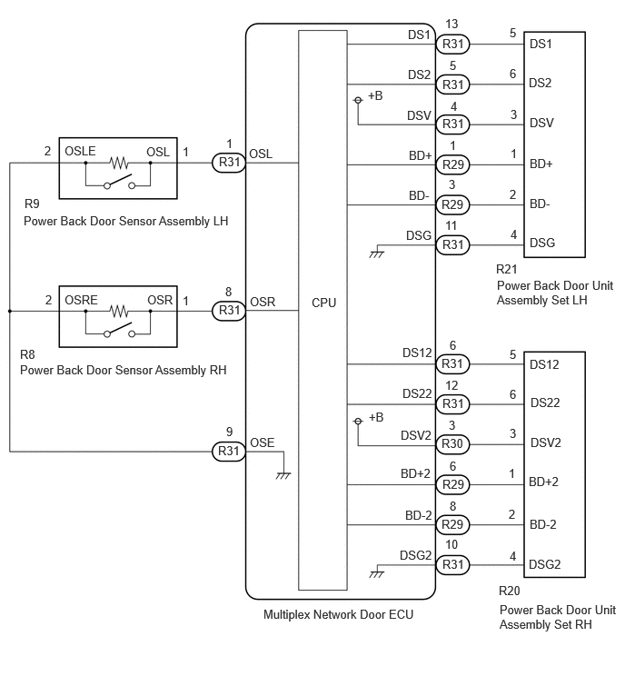
CAUTION / NOTICE / HINT
- NOTICE:
-
If the multiplex network door ECU has been replaced, or if any of the connectors has been disconnected, initialize the power back door system.
PROCEDURE
Check if there are any foreign objects interfering with back door operation.
- Result:
Result Proceed to There are no foreign objects A There are foreign objects B
A
B
Set the power back door system main switch to "Off"
Operate the multi-information display and disable the function.
| Display | Description | Default | Setting | Relevant ECU |
|---|---|---|---|---|
| System settings | Function that enables or disables the power back door operation. | On | On or Off | Multiplex network door ECU |
Check that the back door operates smoothly without catching (does not feel heavy) when manually opened and closed.
- Result:
Proceed to OK NG
OK
NG
Check the Data List to determine if the power back door sensor assembly functions properly.
- Body Electrical > Back Door > Data List
-
Tester Display Measurement Item Range Normal Condition Diagnostic Note PBD Touch Sensor RH Power back door sensor assembly RH signal ON, OFF or Open ON: Power back door sensor assembly RH pressed
OFF: Power back door sensor assembly RH not pressed
Open: Power back door sensor assembly RH circuit open- PBD Touch Sensor LH Power back door sensor assembly LH signal ON, OFF or Open ON: Power back door sensor assembly LH pressed
OFF: Power back door sensor assembly LH not pressed
Open: Power back door sensor assembly LH circuit open-
- Body Electrical > Back Door > Data List
-
Tester Display PBD Touch Sensor RH PBD Touch Sensor LH - 50003 489 1057,1058
- Result:
Result Proceed to On the GTS screen, ON or OFF is displayed accordingly A On the GTS screen, ON or OFF is not displayed accordingly or Open is displayed for power back door sensor assembly RH B On the GTS screen, ON or OFF is not displayed accordingly or Open is displayed for power back door sensor assembly LH C
A
B
C
Using an oscilloscope, check the waveform of each terminal from the rear of the multiplex network door ECU connector.
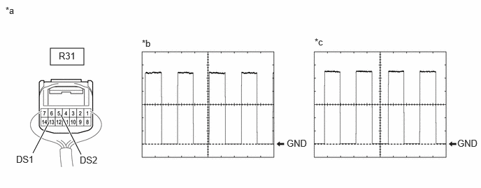
| *a | Component with harness connected
(Multiplex Network Door ECU) |
*b | Waveform (CH1) |
| *c | Waveform (CH2) | - | - |
- Measurement Condition:
Item Condition Tester Connection ·CH1: R31-13 (DS1) - Body ground
·CH2: R31-5 (DS2) - Body ground
Tool Setting 2 V/DIV., 2 ms./DIV. Vehicle Condition Open and close the back door by hand.
- HINT:
- ·
The period changes in accordance to the speed at which the back door is opened and closed by hand.
·The wave height changes in accordance with the auxiliary battery voltage.
- Result:
Proceed to OK NG
OK
NG
Using an oscilloscope, check the waveform of each terminal from the rear of the multiplex network door ECU connector.
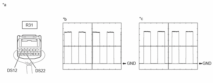
| *a | Component with harness connected
(Multiplex Network Door ECU) |
*b | Waveform (CH1) |
| *c | Waveform (CH2) | - | - |
- Measurement Condition:
Item Condition Tester Connection ·CH1: R31-6 (DS12) - Body ground
·CH2: R31-12 (DS22) - Body ground
Tool Setting 2 V/DIV., 2 ms./DIV. Vehicle Condition Open and close the back door by hand.
- HINT:
- ·
The period changes in accordance to the speed at which the back door is opened and closed by hand.
·The wave height changes in accordance with the auxiliary battery voltage.
- Result:
Proceed to OK NG
OK
NG
- Result:
Proceed to OK NG
OK
NG
Disconnect the R8 power back door sensor assembly RH connector.
Disconnect the R31 multiplex network door ECU connector.
Measure the resistance according to the value(s) in the table below.
- Standard Resistance:
Tester Connection Condition Specified Condition R8-1 (OSR) - R31-8 (OSR) Always Below 1 Ω R8-2 (OSRE) - R31-9 (OSE) Always Below 1 Ω R8-1 (OSR) or R31-8 (OSR) - Body ground Always 10 kΩ or higher R8-2 (OSRE) or R31-9 (OSE) - Body ground Always 10 kΩ or higher
- Result:
Proceed to OK NG
OK
NG
- Result:
Proceed to OK NG
OK
NG
Disconnect the R9 power back door sensor assembly LH connector.
Disconnect the R31 multiplex network door ECU connector.
Measure the resistance according to the value(s) in the table below.
- Standard Resistance:
Tester Connection Condition Specified Condition R9-1 (OSL) - R31-1 (OSL) Always Below 1 Ω R9-2 (OSLE) - R31-9 (OSE) Always Below 1 Ω R9-1 (OSL) or R31-1 (OSL) - Body ground Always 10 kΩ or higher R9-2 (OSLE) or R31-9 (OSE) - Body ground Always 10 kΩ or higher
- Result:
Proceed to OK NG
OK
NG
Visually check the power back door unit assembly set LH/RH to check that there is no obvious damage, bends or fluid leaks.
- OK:
There is no obvious damage, bends or fluid leaks on the power back door unit assembly set LH/RH.
- Result:
Proceed to OK NG
OK
NG