METER / GAUGE / DISPLAY METER / GAUGE SYSTEM(except 12.3 Inch Display) B150013 Fuel Sender Circuit Open
DESCRIPTION
This DTC is stored when the combination meter assembly detects a fuel sender gauge assembly malfunction via a direct line.
| DTC No. | Detection Item | DTC Detection Condition | Trouble Area |
|---|---|---|---|
| B150013 | Fuel Sender Circuit Open | Diagnosis Condition:
·
The ignition switch is ON ·
IG power source voltage is 9.5 V or more Malfunction Status: ·
Voltage signal from fuel sender gauge assembly is 0.2 V or less ·
Voltage signal from fuel sender gauge assembly is 4.7 V or more Malfunction Time: 10 seconds or more |
·
Harness or connector ·
Fuel sender gauge assembly ·
Fuel suction tube with pump and gauge assembly ·
Combination meter assembly |
WIRING DIAGRAM
for HV Model
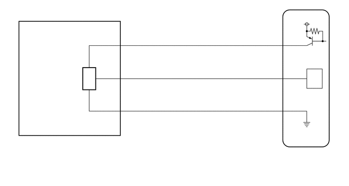
for Gasoline Model (except NR Series Engine)
for Gasoline Model (for NR Series Engine)
CAUTION / NOTICE / HINT
- NOTICE:
- ·
When replacing the combination meter assembly, always replace it with a new one. If a combination meter assembly which was installed to another vehicle is used, the information stored in it will not match the information from the vehicle and a DTC may be stored.
·except NR Series Engine
When replacing the combination meter assembly, update the ECU security key.
PROCEDURE
Choose the model to be inspected.
- Result:
Result Proceed to for HV Model A for Gasoline Model B
A
B
Read the Data List according to the display on the GTS.
- Body Electrical > Combination Meter > Data List
-
Tester Display Measurement Item Range Normal Condition Diagnostic Note Fuel Input Fuel input Min.: 0.00 L, Max.: 655.35 L or Unset ·Fuel receiver gauge indicates F: 37.82 L
·Fuel receiver gauge indicates 3/4: 29.43 L
·Fuel receiver gauge indicates 1/2: 21.04 L
·Fuel receiver gauge indicates 1/4: 12.64 L
·Fuel receiver gauge indicates E: 4.25 L
-
- Body Electrical > Combination Meter > Data List
-
Tester Display Fuel Input - 50003 409 20
- Result:
Result Proceed to Fuel level data can be displayed on the GTS A Fuel level data cannot be displayed on the GTS B
A
B
for 8ZR-FXE: Click hereEngine / Hybrid System>8ZR-FXE (FUEL)>FUEL SENDER GAUGE ASSEMBLY>INSPECTION201906,999999,_51,_080749,_0393859,RM100000001I0FP,
for M20F-FXS, M20G-FXS: Click hereEngine / Hybrid System>M20F-FXS, M20G-FXS (FUEL)>FUEL SENDER GAUGE ASSEMBLY>INSPECTION202307,999999,_51,_146900,_0611209,RM100000002CICF,
- Result:
Proceed to OK NG
OK
NG
for 8ZR-FXE: Click hereEngine / Hybrid System>8ZR-FXE (FUEL)>FUEL SENDER GAUGE ASSEMBLY>REMOVAL202304,999999,_51,_080749,_0393859,RM100000002BCB9,
for M20F-FXS, M20G-FXS: Click hereEngine / Hybrid System>M20F-FXS, M20G-FXS (FUEL)>FUEL SENDER GAUGE ASSEMBLY>REMOVAL202307,999999,_51,_146900,_0611209,RM100000002CICI,
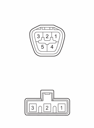
| *a | Component without harness connected
(Fuel Suction Tube with Pump and Gauge Assembly) |
Measure the resistance according to the value(s) in the table below.
- Standard Resistance:
Tester Connection Condition Specified Condition O44-1 (FV) - A-3 Always Below 1 Ω O44-2 (FE) - A-2 Always Below 1 Ω O44-3 (FR) - A-1 Always Below 1 Ω O44-1 (FV) - O44-3 (FR)
or
A-3 - A-1Always 10 kΩ or higher O44-1 (FV) - O44-2 (FE)
or
A-3 - A-2Always 10 kΩ or higher O44-2 (FE) - O44-3 (FR)
or
A-2 - A-1Always 10 kΩ or higher
- Result:
Proceed to OK NG
OK
NG
for 8ZR-FXE: Click hereEngine / Hybrid System>8ZR-FXE (FUEL)>FUEL PUMP>REMOVAL202304,999999,_51,_080749,_0393857,RM100000002BCB8,
for M20F-FXS, M20G-FXS: Click hereEngine / Hybrid System>M20F-FXS, M20G-FXS (FUEL)>FUEL PUMP>REMOVAL202307,999999,_51,_146900,_0611208,RM100000002CICD,
Disconnect the I5 combination meter assembly connector.
Measure the resistance according to the value(s) in the table below.
- Standard Resistance:
Tester Connection Condition Specified Condition O44-1 (FV) - I5-23 (FV) Always Below 1 Ω O44-3 (FR) - I5-7 (FR) Always Below 1 Ω O44-2 (FE) - I5-25 (FE&B) Always Below 1 Ω O44-1 (FV) or I5-23 (FV) - Body ground Always 10 kΩ or higher O44-3 (FR) or I5-7 (FR) - Body ground Always 10 kΩ or higher
- Result:
Proceed to OK NG
OK
NG
Choose the model to be inspected.
- Result:
Result Proceed to except NR Series Engine A for NR Series Engine B
A
B
Read the Data List according to the display on the GTS.
- Body Electrical > Combination Meter > Data List
-
Tester Display Measurement Item Range Normal Condition Diagnostic Note Fuel Input Fuel input Min.: 0.00 L, Max.: 655.35 L or Unset for M15B-FKS, M15C-FKS·Fuel receiver gauge indicates F: 41.86 L
·Fuel receiver gauge indicates 3/4: 32.57 L
·Fuel receiver gauge indicates 1/2: 23.28 L
·Fuel receiver gauge indicates 1/4: 13.99 L
·Fuel receiver gauge indicates E: 4.70 L
for M20A-FKS, M20C-FKS, M20E-FKS·Fuel receiver gauge indicates F: 44.50 L
·Fuel receiver gauge indicates 3/4: 34.63 L
·Fuel receiver gauge indicates 1/2: 24.75 L
·Fuel receiver gauge indicates 1/4: 14.88 L
·Fuel receiver gauge indicates E: 5.00 L
-
- Body Electrical > Combination Meter > Data List
-
Tester Display Fuel Input - 50003 409 20
- Result:
Result Proceed to Fuel level data can be displayed on the GTS A Fuel level data cannot be displayed on the GTS B
A
B
for M15B-FKS: Click hereEngine / Hybrid System>M15B-FKS (FUEL)>FUEL SENDER GAUGE ASSEMBLY>INSPECTION202304,999999,_51,_096202,_0454932,RM10000000293I4,
for M15C-FKS: Click hereEngine / Hybrid System>M15C-FKS (FUEL)>FUEL SENDER GAUGE ASSEMBLY>INSPECTION202304,999999,_51,_096210,_0454942,RM10000000293IR,
for M20A-FKS: Click hereEngine / Hybrid System>M20A-FKS (FUEL)>FUEL SENDER GAUGE ASSEMBLY>INSPECTION202104,999999,_51,_101146,_0469728,RM100000001VJEQ,
for M20C-FKS: Click hereEngine / Hybrid System>M20C-FKS (FUEL)>FUEL SENDER GAUGE ASSEMBLY>INSPECTION202107,999999,_51,_105192,_0482741,RM100000001X44N,
for M20E-FKS: Click hereEngine / Hybrid System>M20E-FKS (FUEL)>FUEL SENDER GAUGE ASSEMBLY>INSPECTION202104,999999,_51,_101156,_0476761,RM100000001WEI9,
- Result:
Proceed to OK NG
OK
NG
for M15B-FKS: Click hereEngine / Hybrid System>M15B-FKS (FUEL)>FUEL SENDER GAUGE ASSEMBLY>REMOVAL202304,999999,_51,_096202,_0454932,RM10000000293I3,
for M15C-FKS: Click hereEngine / Hybrid System>M15C-FKS (FUEL)>FUEL SENDER GAUGE ASSEMBLY>REMOVAL202304,999999,_51,_096210,_0454942,RM10000000293IQ,
for M20A-FKS: Click hereEngine / Hybrid System>M20A-FKS (FUEL)>FUEL SENDER GAUGE ASSEMBLY>REMOVAL202304,999999,_51,_101146,_0469728,RM100000002BCAF,
for M20C-FKS: Click hereEngine / Hybrid System>M20C-FKS (FUEL)>FUEL SENDER GAUGE ASSEMBLY>REMOVAL202304,999999,_51,_105192,_0482741,RM100000002BCAU,
for M20E-FKS: Click hereEngine / Hybrid System>M20E-FKS (FUEL)>FUEL SENDER GAUGE ASSEMBLY>REMOVAL202304,999999,_51,_101156,_0476761,RM100000002BCB5,
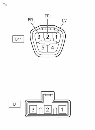
| *a | Component without harness connected
(Fuel Suction Tube with Pump and Gauge Assembly) |
Measure the resistance according to the value(s) in the table below.
- Standard Resistance:
Tester Connection Condition Specified Condition O44-1 (FV) - B-3 Always Below 1 Ω O44-2 (FE) - B-2 Always Below 1 Ω O44-3 (FR) - B-1 Always Below 1 Ω O44-1 (FV) - O44-3 (FR)
or
B-3 - B-1Always 10 kΩ or higher O44-1 (FV) - O44-2 (FE)
or
B-3 - B-2Always 10 kΩ or higher O44-2 (FE) - O44-3 (FR)
or
B-2 - B-1Always 10 kΩ or higher
- Result:
Proceed to OK NG
OK
NG
for M15B-FKS: Click hereEngine / Hybrid System>M15B-FKS (FUEL)>FUEL PUMP>REMOVAL202304,999999,_51,_096202,_0454928,RM10000000293HG,
for M15C-FKS: Click hereEngine / Hybrid System>M15C-FKS (FUEL)>FUEL PUMP>REMOVAL202304,999999,_51,_096210,_0454938,RM10000000293IC,
for M20A-FKS: Click hereEngine / Hybrid System>M20A-FKS (FUEL)>FUEL PUMP>REMOVAL202304,999999,_51,_101146,_0469725,RM100000002BCAA,
for M20C-FKS: Click hereEngine / Hybrid System>M20C-FKS (FUEL)>FUEL PUMP>REMOVAL202304,999999,_51,_105192,_0482737,RM100000002BCAO,
for M20E-FKS: Click hereEngine / Hybrid System>M20E-FKS (FUEL)>FUEL PUMP>REMOVAL202304,999999,_51,_101156,_0476758,RM100000002BCB0,
Disconnect the I5 combination meter assembly connector.
Measure the resistance according to the value(s) in the table below.
- Standard Resistance:
Tester Connection Condition Specified Condition O44-1 (FV) - I5-23 (FV) Always Below 1 Ω O44-3 (FR) - I5-7 (FR) Always Below 1 Ω O44-2 (FE) - I5-25 (FE&B) Always Below 1 Ω O44-1 (FV) or I5-23 (FV) - Body ground Always 10 kΩ or higher O44-3 (FR) or I5-7 (FR) - Body ground Always 10 kΩ or higher
- Result:
Proceed to OK NG
OK
NG
Read the Data List according to the display on the GTS.
- Body Electrical > Combination Meter > Data List
-
Tester Display Measurement Item Range Normal Condition Diagnostic Note Fuel Input Fuel input Min.: 0.00 L, Max.: 655.35 L or Unset ·Fuel receiver gauge indicates F: 44.00 L
·Fuel receiver gauge indicates 3/4: 34.11 L
·Fuel receiver gauge indicates 1/2: 24.40 L
·Fuel receiver gauge indicates 1/4: 14.69 L
·Fuel receiver gauge indicates E: 5.00 L
-
- Body Electrical > Combination Meter > Data List
-
Tester Display Fuel Input - 50003 409 20
- Result:
Result Proceed to Fuel level data can be displayed on the GTS A Fuel level data cannot be displayed on the GTS B
A
B
- Result:
Proceed to OK NG
OK
NG
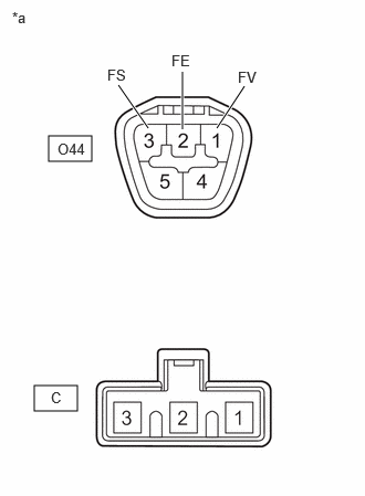
| *a | Component without harness connected
(Fuel Suction Tube with Pump and Gauge Assembly) |
Measure the resistance according to the value(s) in the table below.
- Standard Resistance:
Tester Connection Condition Specified Condition O44-1 (FV) - C-3 Always Below 1 Ω O44-2 (FE) - C-2 Always Below 1 Ω O44-3 (FS) - C-1 Always Below 1 Ω O44-1 (FV) - O44-3 (FS)
or
C-3 - C-1Always 10 kΩ or higher O44-1 (FV) - O44-2 (FE)
or
C-3 - C-2Always 10 kΩ or higher O44-2 (FE) - O44-3 (FS)
or
C-2 - C-1Always 10 kΩ or higher
- Result:
Proceed to OK NG
OK
NG
Disconnect the I4 combination meter assembly connector.
Measure the resistance according to the value(s) in the table below.
- Standard Resistance:
Tester Connection Condition Specified Condition O44-1 (FV) - I4-14 (FV) Always Below 1 Ω O44-3 (FS) - I4-31 (FR) Always Below 1 Ω O44-2 (FE) - I4-24 (FE&B) Always Below 1 Ω O44-1 (FV) or I4-14 (FV) - Body ground Always 10 kΩ or higher O44-3 (FS) or I4-31 (FR) - Body ground Always 10 kΩ or higher
- Result:
Proceed to OK NG
OK
NG