NR Series FUEL FUEL SENDER GAUGE ASSEMBLY INSPECTION
PROCEDURE

 83320
1.INSPECT FUEL SENDER GAUGE ASSEMBLY
83320
1.INSPECT FUEL SENDER GAUGE ASSEMBLY
- CAUTION:
-
Perform the inspection in a well-ventilated area.
-
Do not perform the inspection near an open flame.
Check that the float moves smoothly between F and E.
Check the fuel sender gauge assembly voltage.
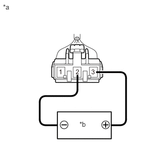
| *a | Component without harness connected
(Fuel Sender Gauge Assembly) |
| *b | Voltage Applied between Terminals |
Apply 5 V between terminals 2 and 3.
- NOTICE:
- ·
Be careful when connecting the leads, as the fuel sender gauge assembly may be damaged if the leads are connected to the wrong terminals.
·Do not apply more than 6 V to terminals 2 or 3.
- HINT:
-
If a stable power supply is not available, connect 4 nickel-metal hydride batteries (1.2 V each) or equivalent in series.
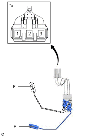
| *a | Component without harness connected
(Fuel Sender Gauge Assembly) |
Measure the voltage according to the value(s) in the table below.
- Standard Voltage:
Tester Connection Float Level Specified Condition 1 - 2 F 4.255 to 4.605 V* Between F and E 0.345 to 4.605 V* (Gradually changes) E 0.345 to 0.695 V*
*: The output voltage changes depending on the voltage applied to the terminals.
Output voltage (F) = (0.851 x Voltage applied to terminals) to (0.921 x Voltage applied to terminals)
Output voltage (E) = (0.069 x Voltage applied to terminals) to (0.139 x Voltage applied to terminals)
If the result is not as specified, replace the fuel sender gauge assembly.