FRONT SUSPENSION FRONT STABILIZER BAR REMOVAL
CAUTION / NOTICE / HINT
The necessary procedures (adjustment, calibration, initialization, or registration) that must be performed after parts are removed and installed, or replaced during front stabilizer bar removal/installation are shown below.
| Replaced Part or Performed Procedure | Necessary Procedure | Effect/Inoperative Function when Necessary Procedure not Performed | Link |
|---|---|---|---|
|
*: The vehicle height changes because of tire replacement. *1: If matchmarks were not placed when removing parts related to steering operation, perform end position initial setting. |
|||
| Front wheel alignment adjustment | 1.
Perform "Reset Memory" 2.
Perform "Calibration" |
·
DTCs are stored ·
ABS warning light illuminates ·
Brake system warning light (yellow indicator) illuminates ·
Slip indicator light illuminates ·
Electronically controlled brake system disabled or malfunctions |
( 202304,999999,_54,_080770,_0392591,RM100000002B671,) 202304,999999,_54,_080770,_0392591,RM100000002B671,)
|
·
Tires ·
Suspension parts |
Rear television camera assembly optical axis (Back camera position setting)* | Parking Assist Monitor System | (202304,999999,_56,_080754,_0596561,RM100000002AX0C,)
|
| Parking assist ECU initialization | Panoramic View Monitor System | (202307,999999,_56,_080754,_0612151,RM100000002CL9H,)
|
|
·
Steering gear assembly*1 ·
No. 2 steering intermediate shaft assembly*1 |
End position initial setting | - | (202307,999999,_55,_080761,_0392075,RM100000002CNVO,)
|
| Replaced Part or Performed Procedure | Necessary Procedure | Effect/Inoperative Function when Necessary Procedure not Performed | Link |
|---|---|---|---|
|
*: The vehicle height changes because of tire replacement. *1: If matchmarks were not placed when removing parts related to steering operation, perform end position initial setting. |
|||
| Front wheel alignment adjustment | for NR Series
·
Perform "Reset Memory" ·
Perform acceleration sensor zero point calibration and store system information memorization |
·
VSC is disabled or malfunctions ·
DTCs are output ·
Slip indicator light illuminates ·
ABS warning light illuminates |
(202304,999999,_54,_080770,_0599814,RM100000002BA8F,)
|
except NR Series
·
Perform "Reset Memory" ·
Perform "Calibration" |
·
VSC is disabled or malfunctions ·
DTCs are output ·
Slip indicator light illuminates ·
ABS warning light illuminates |
(202304,999999,_54,_080770,_0599811,RM100000002B9XU,)
|
|
·
Tires ·
Suspension parts |
Rear television camera assembly optical axis (Back camera position setting)* | Parking Assist Monitor System | (202304,999999,_56,_080754,_0596561,RM100000002AX0C,)
|
except NR Series
·
Steering gear assembly*1 ·
No. 2 steering intermediate shaft assembly*1 |
End position initial setting | - | (202304,999999,_55,_080761,_0392052,RM100000002B8PZ,)
|
PROCEDURE

 51201
1.REMOVE FRONT SUSPENSION CROSSMEMBER SUB-ASSEMBLY
51201
1.REMOVE FRONT SUSPENSION CROSSMEMBER SUB-ASSEMBLY
48810
2.REMOVE FRONT STABILIZER LINK ASSEMBLY LH
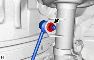
Remove the nut and front stabilizer link assembly LH from the front shock absorber assembly.
- NOTICE:
-
Do not damage the boot of the ball joint.
- HINT:
-
If the ball joint turns together with the nut, use a 6 mm hexagon socket wrench to hold the stud bolt.
48820B
3.REMOVE FRONT STABILIZER LINK ASSEMBLY RH
- HINT:
-
Perform the same procedure as for the LH side.
4.REMOVE STEERING LINK ASSEMBLY
48829A
5.REMOVE FRONT NO. 1 STABILIZER BRACKET LH
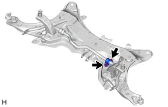
Remove the 2 bolts and front stabilizer bracket LH from the front suspension crossmember sub-assembly.
48824A
6.REMOVE FRONT NO. 1 STABILIZER BRACKET RH
- HINT:
-
Perform the same procedure as for the LH side.
48811
7.REMOVE FRONT STABILIZER BAR
Remove the front stabilizer bar with 2 front stabilizer bar bushings from the front suspension crossmember sub-assembly.
48815E
8.REMOVE FRONT STABILIZER BAR BUSHING LH
Remove the front stabilizer bar bushing LH from the front stabilizer bar.
48815D
9.REMOVE FRONT STABILIZER BAR BUSHING RH
- HINT:
-
Perform the same procedure as for the LH side.