STEERING GEAR / LINKAGE STEERING GEAR INSTALLATION
PROCEDURE

 45047
1.INSTALL TIE ROD END SUB-ASSEMBLY LH
45047
1.INSTALL TIE ROD END SUB-ASSEMBLY LH
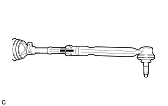
| *a | Matchmark |
Install the lock nut and tie rod end sub-assembly LH to the steering gear assembly until the matchmarks are aligned.
- HINT:
-
After adjusting the toe-in, tighten the lock nut.
45046
2.INSTALL TIE ROD END SUB-ASSEMBLY RH
- HINT:
-
Perform the same procedure as for the LH side.
3.INSTALL STEERING LINK ASSEMBLY
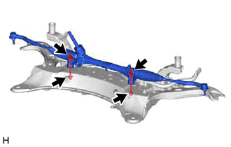
Install the steering link assembly to the front suspension crossmember sub-assembly with the 2 bolts and 2 new nuts.
- Torque:
- 133 N*m (1356 kgf*cm, 98 ft.*lbf)
- NOTICE:
- ·
Because the nut has its own stopper, do not turn the nut. Tighten the bolt with the nut secured.
·Make sure to tighten the bolts starting from the left side of the vehicle.
45025D
4.INSTALL NO. 1 STEERING COLUMN HOLE COVER SUB-ASSEMBLY
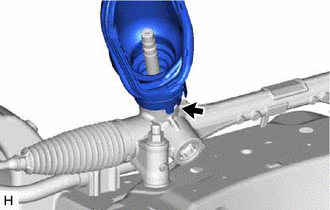
Align the protrusion of the steering link assembly with the hole of the No. 1 steering column hole cover sub-assembly, and install the No. 1 steering column hole cover sub-assembly to the steering link assembly.
- HINT:
-
Check that the No. 1 steering column hole cover sub-assembly is securely installed.
51201
5.INSTALL FRONT SUSPENSION CROSSMEMBER SUB-ASSEMBLY
48069
6.CONNECT FRONT LOWER NO. 1 SUSPENSION ARM SUB-ASSEMBLY LH
48068
7.CONNECT FRONT LOWER NO. 1 SUSPENSION ARM SUB-ASSEMBLY RH
- HINT:
-
Perform the same procedure as for the LH side.
45047
8.CONNECT TIE ROD END SUB-ASSEMBLY LH
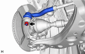
Connect the tie rod end sub-assembly LH to the steering knuckle LH with the nut.
- Torque:
- 49 N*m (500 kgf*cm, 36 ft.*lbf)
- NOTICE:
- ·
Do not damage the ball joint dust cover.
·Further tighten the nut up to 60° if the holes for the cotter pin are not aligned.
Install a new cotter pin.
45046
9.CONNECT TIE ROD END SUB-ASSEMBLY RH
- HINT:
-
Perform the same procedure as for the LH side.
48810
10.CONNECT FRONT STABILIZER LINK ASSEMBLY LH
48820B
11.CONNECT FRONT STABILIZER LINK ASSEMBLY RH
- HINT:
-
Perform the same procedure as for the LH side.
51108A
12.INSTALL REAR SIDE RAIL REINFORCEMENT SUB-ASSEMBLY LH
51107A
13.INSTALL REAR SIDE RAIL REINFORCEMENT SUB-ASSEMBLY RH
- HINT:
-
Perform the same procedure as for the LH side.
51444A
14.INSTALL REAR ENGINE UNDER COVER LH
for M15B-FKS: Click hereEngine / Hybrid System>M15B-FKS (ENGINE MECHANICAL)>ENGINE ASSEMBLY>INSTALLATION202304,999999,_51,_096197,_0454892,RM100000002BBF1_01_0387,
for M15C-FKS: Click hereEngine / Hybrid System>M15C-FKS (ENGINE MECHANICAL)>ENGINE ASSEMBLY>INSTALLATION202304,999999,_51,_096206,_0454902,RM100000002BBQF_01_0387,
for M20A-FKS: Click hereEngine / Hybrid System>M20A-FKS (ENGINE MECHANICAL)>ENGINE ASSEMBLY>INSTALLATION202304,999999,_51,_101145,_0470307,RM100000002BFCZ_01_0387,
for M20C-FKS: Click hereEngine / Hybrid System>M20C-FKS (ENGINE MECHANICAL)>ENGINE ASSEMBLY>INSTALLATION202304,999999,_51,_105191,_0481157,RM100000002BFD2_01_0387,
for M20E-FKS: Click hereEngine / Hybrid System>M20E-FKS (ENGINE MECHANICAL)>ENGINE ASSEMBLY>INSTALLATION202304,999999,_51,_101154,_0476817,RM100000002BFD9_01_0387,
for M20F-FXS, M20G-FXS: Click hereEngine / Hybrid System>M20F-FXS, M20G-FXS (ENGINE MECHANICAL)>ENGINE ASSEMBLY>INSTALLATION202307,999999,_51,_146897,_0611496,RM100000002CJ21_01_0387,
for 8ZR-FXE: Click hereEngine / Hybrid System>8ZR-FXE (ENGINE MECHANICAL)>ENGINE ASSEMBLY>INSTALLATION202304,999999,_51,_080726,_0391619,RM100000002B5Z9_01_0389,
for NR Series Engine: Click hereEngine / Hybrid System>NR Series (ENGINE MECHANICAL)>ENGINE ASSEMBLY>INSTALLATION202304,999999,_51,_080739,_0391935,RM100000002BCNA_01_0448,
51443C
15.INSTALL REAR ENGINE UNDER COVER RH
for M15B-FKS: Click hereEngine / Hybrid System>M15B-FKS (ENGINE MECHANICAL)>ENGINE ASSEMBLY>INSTALLATION202304,999999,_51,_096197,_0454892,RM100000002BBF1_01_0388,
for M15C-FKS: Click hereEngine / Hybrid System>M15C-FKS (ENGINE MECHANICAL)>ENGINE ASSEMBLY>INSTALLATION202304,999999,_51,_096206,_0454902,RM100000002BBQF_01_0388,
for M20A-FKS: Click hereEngine / Hybrid System>M20A-FKS (ENGINE MECHANICAL)>ENGINE ASSEMBLY>INSTALLATION202304,999999,_51,_101145,_0470307,RM100000002BFCZ_01_0388,
for M20C-FKS: Click hereEngine / Hybrid System>M20C-FKS (ENGINE MECHANICAL)>ENGINE ASSEMBLY>INSTALLATION202304,999999,_51,_105191,_0481157,RM100000002BFD2_01_0388,
for M20E-FKS: Click hereEngine / Hybrid System>M20E-FKS (ENGINE MECHANICAL)>ENGINE ASSEMBLY>INSTALLATION202304,999999,_51,_101154,_0476817,RM100000002BFD9_01_0388,
for M20F-FXS, M20G-FXS: Click hereEngine / Hybrid System>M20F-FXS, M20G-FXS (ENGINE MECHANICAL)>ENGINE ASSEMBLY>INSTALLATION202307,999999,_51,_146897,_0611496,RM100000002CJ21_01_0388,
for 8ZR-FXE: Click hereEngine / Hybrid System>8ZR-FXE (ENGINE MECHANICAL)>ENGINE ASSEMBLY>INSTALLATION202304,999999,_51,_080726,_0391619,RM100000002B5Z9_01_0434,
for NR Series Engine: Click hereEngine / Hybrid System>NR Series (ENGINE MECHANICAL)>ENGINE ASSEMBLY>INSTALLATION202304,999999,_51,_080739,_0391935,RM100000002BCNA_01_0451,
51410
16.INSTALL NO. 1 ENGINE UNDER COVER ASSEMBLY
for M15B-FKS: Click hereEngine / Hybrid System>M15B-FKS (ENGINE MECHANICAL)>ENGINE ASSEMBLY>INSTALLATION202304,999999,_51,_096197,_0454892,RM100000002BBF1_01_0389,
for M15C-FKS: Click hereEngine / Hybrid System>M15C-FKS (ENGINE MECHANICAL)>ENGINE ASSEMBLY>INSTALLATION202304,999999,_51,_096206,_0454902,RM100000002BBQF_01_0389,
for M20A-FKS: Click hereEngine / Hybrid System>M20A-FKS (ENGINE MECHANICAL)>ENGINE ASSEMBLY>INSTALLATION202304,999999,_51,_101145,_0470307,RM100000002BFCZ_01_0389,
for M20C-FKS: Click hereEngine / Hybrid System>M20C-FKS (ENGINE MECHANICAL)>ENGINE ASSEMBLY>INSTALLATION202304,999999,_51,_105191,_0481157,RM100000002BFD2_01_0389,
for M20E-FKS: Click hereEngine / Hybrid System>M20E-FKS (ENGINE MECHANICAL)>ENGINE ASSEMBLY>INSTALLATION202304,999999,_51,_101154,_0476817,RM100000002BFD9_01_0389,
for M20F-FXS, M20G-FXS: Click hereEngine / Hybrid System>M20F-FXS, M20G-FXS (ENGINE MECHANICAL)>ENGINE ASSEMBLY>INSTALLATION202307,999999,_51,_146897,_0611496,RM100000002CJ21_01_0389,
for 8ZR-FXE: Click hereEngine / Hybrid System>8ZR-FXE (ENGINE MECHANICAL)>ENGINE ASSEMBLY>INSTALLATION202304,999999,_51,_080726,_0391619,RM100000002B5Z9_01_0392,
for NR Series Engine: Click hereEngine / Hybrid System>NR Series (ENGINE MECHANICAL)>ENGINE ASSEMBLY>INSTALLATION202304,999999,_51,_080739,_0391935,RM100000002BCNA_01_0452,
45025D
17.CONNECT NO. 1 STEERING COLUMN HOLE COVER SUB-ASSEMBLY
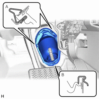
Engage the clip (B) to the vehicle body.
Engage the clip (A) to install the No. 1 steering column hole cover sub-assembly to the vehicle body.
- NOTICE:
- ·
Be careful not to damage the lip of the No. 1 steering column hole cover sub-assembly.
·Check that the No. 1 steering column hole cover sub-assembly is securely installed.
·Check that the No. 1 steering column hole cover sub-assembly and vehicle body are in close contact with one another.
45260
18.CONNECT NO. 2 STEERING INTERMEDIATE SHAFT ASSEMBLY
45259A
19.INSTALL COLUMN HOLE COVER SILENCER SHEET
20.INSTALL FRONT WHEELS
21.INSPECT AND ADJUST FRONT WHEEL ALIGNMENT
22.PERFORM INITIALIZATION
| Parking Assist Monitor System | ( 202304,999999,_56,_080754,_0596561,RM100000002AX0C,) 202304,999999,_56,_080754,_0596561,RM100000002AX0C,)
|
| Panoramic View Monitor System | (202307,999999,_56,_080754,_0612151,RM100000002CL9H,)
|
| Parking Assist Monitor System | (202304,999999,_56,_080754,_0596561,RM100000002AX0C,)
|
23. PERFORM END POSITION INITIAL SETTING
for HV Model: Click hereSteering>POWER ASSIST SYSTEMS>POWER STEERING SYSTEM (for HV Model)>CALIBRATION202307,999999,_55,_080761,_0392075,RM100000002CNVO,
for Gasoline Model, except NR Series: Click hereSteering>POWER ASSIST SYSTEMS>POWER STEERING SYSTEM (for Gasoline Model)>CALIBRATION202304,999999,_55,_080761,_0392052,RM100000002B8PZ,