HEATING / AIR CONDITIONING CONDENSER REMOVAL
CAUTION / NOTICE / HINT
The necessary procedures (adjustment, calibration, initialization, or registration) that must be performed after parts are removed and installed, or replaced during cooler condenser assembly removal/installation are shown below.
| Replaced Part or Performed Procedures | Necessary Procedures | Effect/Inoperative Function When Necessary Procedures are not Performed | Link |
|---|---|---|---|
|
*: Even when not replacing the part, it is necessary to perform the specified necessary procedures after installation. |
|||
·
Front television camera assembly* ·
Front bumper assembly* ·
Radiator grille sub-assembly* |
Front television camera view adjustment | Panoramic View Monitor System | ( 202307,999999,_56,_080754,_0612151,RM100000002CL9H,) 202307,999999,_56,_080754,_0612151,RM100000002CL9H,)
|
Replacement or removal and installation of 2 or more parts:
·
Front television camera assembly, radiator grille sub-assembly or front bumper assembly ·
Side television camera assembly LH or outer rear view mirror assembly LH ·
Side television camera assembly RH or outer rear view mirror assembly RH ·
Rear television camera assembly |
Television camera view adjustment | Panoramic View Monitor System | (202307,999999,_56,_080754,_0612151,RM100000002CL9H,)
|
PROCEDURE

 1.RECOVER REFRIGERANT FROM REFRIGERATION SYSTEM
2.REMOVE HEADLIGHT ASSEMBLY LH
for TFTM Made:
for GTMC Made:
3.REMOVE HEADLIGHT ASSEMBLY RH
- HINT:
-
Use the same procedure as for the LH side.
17753
4.REMOVE INLET NO. 3 AIR CLEANER (for NR Series Engine)
17751
5.REMOVE INLET NO. 1 AIR CLEANER (for NR Series Engine)
17751
6.REMOVE INLET NO. 1 AIR CLEANER (for M15B-FKS)
17751
7.REMOVE INLET NO. 1 AIR CLEANER (for M15C-FKS)
17751
8.REMOVE INLET NO. 1 AIR CLEANER (for M20A-FKS)
17751
9.REMOVE INLET NO. 1 AIR CLEANER (for M20C-FKS)
17751
10.REMOVE INLET NO. 1 AIR CLEANER (for M20E-FKS)
17751
11.REMOVE INLET NO. 1 AIR CLEANER (for M20F-FXS, M20G-FXS)
17752
12.REMOVE INLET NO. 2 AIR CLEANER (for 8ZR-FXE)
52611
13.REMOVE FRONT BUMPER ENERGY ABSORBER (for TFTM Made)
for COROLLA:
for ALLION:
52611
14.REMOVE FRONT BUMPER ENERGY ABSORBER (for GTMC Made)
except Sport Package:
for Sport Package:
52131A
15.REMOVE FRONT BUMPER REINFORCEMENT (for TFTM Made)
for COROLLA:
for ALLION:
52131A
16.REMOVE FRONT BUMPER REINFORCEMENT (for GTMC Made)
53510
17.REMOVE HOOD LOCK ASSEMBLY
53205
18.REMOVE UPPER RADIATOR SUPPORT SUB-ASSEMBLY
for NR Series Engine:
for 8ZR-FXE:
for M15B-FKS:
for M15C-FKS:
for M20A-FKS:
for M20C-FKS:
for M20E-FKS:
for M20F-FXS, M20G-FXS:
16594A
19.REMOVE NO. 2 RADIATOR AIR GUIDE (for NR Series Engine)
16594A
20.REMOVE NO. 2 RADIATOR AIR GUIDE (for M15B-FKS)
16594A
21.REMOVE NO. 2 RADIATOR AIR GUIDE (for M15C-FKS)
16594A
22.REMOVE NO. 2 RADIATOR AIR GUIDE (for 8ZR-FXE)
16594A
23.REMOVE NO. 2 RADIATOR AIR GUIDE (for M20A-FKS)
16594A
24.REMOVE NO. 2 RADIATOR AIR GUIDE (for M20C-FKS)
16594A
25.REMOVE NO. 2 RADIATOR AIR GUIDE (for M20E-FKS)
16594A
26.REMOVE NO. 2 RADIATOR AIR GUIDE (for M20F-FXS, M20G-FXS)
16595B
27.REMOVE NO. 1 RADIATOR AIR GUIDE LH
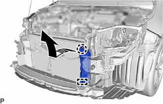

|
Remove in this Direction |
Disengage the claw and guide, and remove the No. 1 radiator air guide LH as shown in the illustration.
16593B
28.REMOVE NO. 1 RADIATOR AIR GUIDE RH
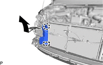
|
|
Remove in this Direction |
Disengage the claw and guide, and remove the No. 1 radiator air guide RH as shown in the illustration.
88703
29.DISCONNECT DISCHARGE HOSE SUB-ASSEMBLY
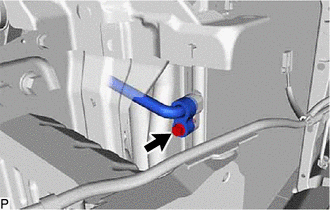
Remove the bolt and disconnect the discharge hose sub-assembly from the cooler condenser assembly.
Remove the O-ring from the discharge hose sub-assembly.
- NOTICE:
-
Seal the openings of the disconnected parts using vinyl tape to prevent entry of moisture and foreign matter.
88716A
30.DISCONNECT COOLER REFRIGERANT LIQUID PIPE A
While pressing the end of the cooler refrigerant liquid pipe A into the end of the cooler condenser assembly, use pliers to squeeze together both sides of the piping clamp until it breaks apart.
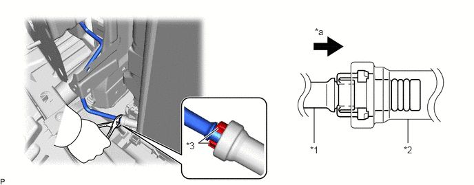
| *1 | Cooler Refrigerant Liquid Pipe A | *2 | Cooler Condenser Assembly |
| *3 | Piping Clamp | - | - |
| *a | Press In | - | - |
- NOTICE:
- ·
If any foreign matter is attached to the connecting parts, brush it off or use compressed air to remove it before disconnecting the parts.
·Make sure that fragments of the piping clamp do not enter the piping.
Disconnect the cooler refrigerant liquid pipe A.
- NOTICE:
-
Remove any foreign matter from the connecting parts of the cooler refrigerant liquid pipe A and cooler condenser assembly.
Remove the 2 O-rings from the cooler refrigerant liquid pipe A.
- NOTICE:
-
Seal the openings of the disconnected parts with vinyl tape to prevent entry of moisture and foreign matter.
Remove the piping clamp.
88460
31.REMOVE COOLER CONDENSER ASSEMBLY
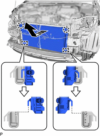
|
|
Remove in this Direction |
Disengage the 2 claws and 2 guides, and remove the cooler condenser assembly as shown in the illustration.
- NOTICE:
-
Do not damage the cooler condenser assembly or radiator assembly when removing the cooler condenser assembly.