RM3660EC _56 Audio / Visual / Telematics _080751 AUDIO / VIDEO _0599626 AUDIO AND VISUAL SYSTEM(for 10.25 Inch Display) J

AUDIO / VIDEO  AUDIO AND VISUAL SYSTEM(for 10.25 Inch Display)  Speaker Circuit  


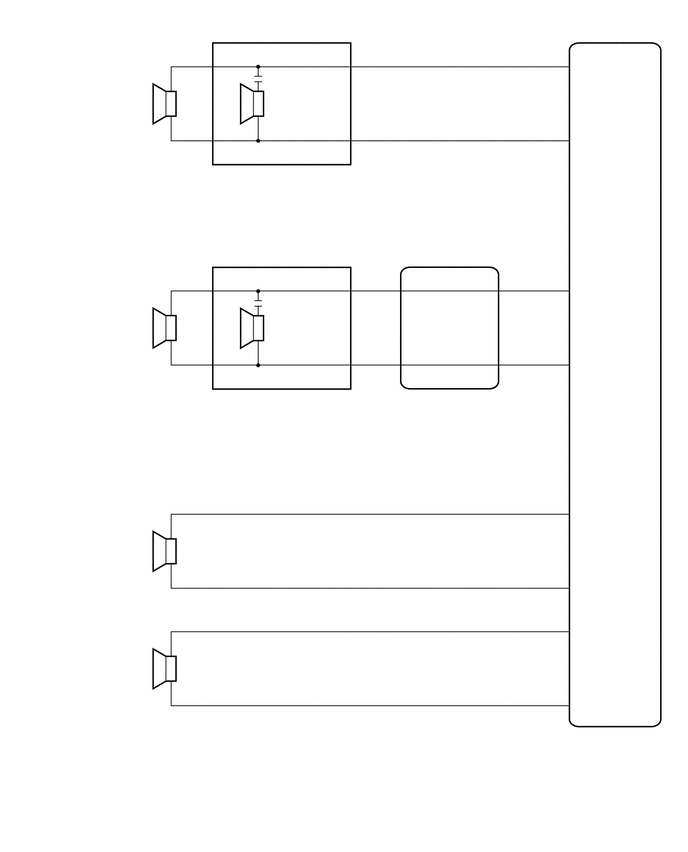
WIRING DIAGRAM

for 4 Speakers
E475544
0.229,0.896 1.51,1.281 1.281,0.385 10 false Front No. 1 Speaker Assembly LH 0.219,3.24 1.5,3.625 1.281,0.385 10 false Front No. 1 Speaker Assembly RH 0.229,0.698 0.51,0.896 0.281,0.198 10 false L1 1.583,0.677 1.865,0.875 0.281,0.198 10 false 2 1.583,1.323 1.865,1.521 0.281,0.198 10 false 1 1.594,3.646 1.875,3.844 0.281,0.198 10 false 1 1.583,5.969 1.865,6.167 0.281,0.198 10 false 1 1.583,7.198 1.865,7.396 0.281,0.198 10 false 1 1.594,3.031 1.875,3.229 0.281,0.198 10 false 2 1.594,5.333 1.875,5.531 0.281,0.198 10 false 2 1.583,6.552 1.865,6.75 0.281,0.198 10 false 2 0.208,3.063 0.49,3.26 0.281,0.198 10 false K1 0.625,5.406 0.906,5.604 0.281,0.198 10 false N4 0.635,5.563 1.521,6 0.885,0.438 10 false Rear Speaker Assembly LH 0.635,6.615 0.917,6.813 0.281,0.198 10 false M4 0.656,6.76 1.542,7.198 0.885,0.438 10 false Rear Speaker Assembly RH 5.74,7.156 6.021,7.354 0.281,0.198 10 false 9 5.76,6.396 6.042,6.594 0.281,0.198 10 false 4 5.76,5.948 6.042,6.146 0.281,0.198 10 false 8 5.75,5.167 6.031,5.365 0.281,0.198 10 false 3 5.771,3.615 6.052,3.813 0.281,0.198 10 false 6 5.76,2.844 6.042,3.042 0.281,0.198 10 false 1 5.75,1.271 6.031,1.469 0.281,0.198 10 false 7 5.76,0.5 6.042,0.698 0.281,0.198 10 false 2 5.969,0.563 6.26,0.76 0.292,0.198 10 false FL+ 5.99,1.333 6.271,1.531 0.281,0.198 10 false FL- 5.979,2.917 6.302,3.115 0.323,0.198 10 false FR+ 5.979,3.677 6.26,3.885 0.281,0.208 10 false FR- 5.969,5.25 6.281,5.448 0.313,0.198 10 false RL+ 5.969,6.021 6.24,6.24 0.271,0.219 10 false RL- 5.979,6.469 6.302,6.667 0.323,0.198 10 false RR+ 5.969,7.229 6.26,7.427 0.292,0.198 10 false RR- 5.854,7.573 6.323,7.875 0.469,0.302 10 false I211 5.833,7.729 6.969,8.302 1.135,0.573 10 false Radio and Display Receiver Assembly 4.073,4.073 4.385,4.25 0.313,0.177 10 false I149 4.083,4.24 5.625,4.542 1.542,0.302 10 false Telematics Transceiver 4.833,3.594 5.271,3.802 0.438,0.208 10 false SPI- 4.823,2.844 5.26,3.052 0.438,0.208 10 false SPI+ 4.25,2.833 4.688,3.042 0.438,0.208 10 false SPO+ 4.24,3.594 4.677,3.802 0.438,0.208 10 false SPO- 4.01,3.604 4.292,3.802 0.281,0.198 10 false 4 4,2.844 4.281,3.042 0.281,0.198 10 false 3 5.24,2.833 5.521,3.031 0.281,0.198 10 false 1 5.26,3.604 5.542,3.802 0.281,0.198 10 false 2

for 6 Speakers
E554367
5.99,2.906 6.323,3.115 0.333,0.208 10 false FR+ 5.76,2.823 6.177,3.031 0.417,0.208 10 false 1 5.76,3.594 6.177,3.802 0.417,0.208 10 false 6 5.75,0.5 6.167,0.708 0.417,0.208 10 false 2 5.75,1.26 6.167,1.469 0.417,0.208 10 false 7 5.854,7.573 6.333,7.958 0.479,0.385 10 false I211 5.854,7.729 6.969,8.281 1.115,0.552 10 false Radio and Display Receiver Assembly 3.719,0.5 4.135,0.708 0.417,0.208 10 false 4 3.708,1.26 4.125,1.469 0.417,0.208 10 false 2 1.583,1.302 2,1.51 0.417,0.208 10 false 1 2.073,0.5 2.49,0.708 0.417,0.208 10 false 3 2.813,0.5 4.063,0.74 1.25,0.24 10 false +*1, TWL+*2 2.49,1.615 2.906,1.823 0.417,0.208 10 false - 0.229,0.698 0.646,0.906 0.417,0.208 10 false L1 0.229,0.875 1.51,1.24 1.281,0.365 10 false Front No. 1 Speaker Assembly LH 0.25,3.021 0.667,3.229 0.417,0.208 10 false K1 0.635,5.375 1.052,5.583 0.417,0.208 10 false N4 0.573,6.615 0.99,6.823 0.417,0.208 10 false M4 0.25,3.219 1.51,3.594 1.26,0.375 10 false Front No. 1 Speaker Assembly RH 0.635,5.542 1.521,5.917 0.885,0.375 10 false Rear Speaker Assembly LH 0.583,6.792 1.479,7.167 0.896,0.375 10 false Rear Speaker Assembly RH 2.292,0.49 2.708,0.698 0.417,0.208 10 false + 2.094,2.833 2.51,3.042 0.417,0.208 10 false 3 2.083,3.594 2.5,3.802 0.417,0.208 10 false 1 3.698,3.604 4.115,3.813 0.417,0.208 10 false 2 3.708,2.833 4.125,3.042 0.417,0.208 10 false 4 2.781,2.844 3.854,3.063 1.073,0.219 10 false +*1, TWR+*2 4.854,3.594 5.271,3.802 0.417,0.208 10 false SPI- 2.281,3.583 2.698,3.792 0.417,0.208 10 false - 2.281,2.823 2.698,3.031 0.417,0.208 10 false + 5.979,3.677 6.26,3.885 0.281,0.208 10 false FR- 5.969,0.563 6.26,0.771 0.292,0.208 10 false FL+ 5.99,1.333 6.25,1.542 0.26,0.208 10 false FL- 1.594,5.354 2.01,5.563 0.417,0.208 10 false 2 1.583,6.563 2,6.771 0.417,0.208 10 false 2 1.583,5.969 2,6.177 0.417,0.208 10 false 1 1.583,7.198 2,7.406 0.417,0.208 10 false 1 5.969,7.219 6.26,7.406 0.292,0.188 10 false RR- 5.979,6.458 6.313,6.646 0.333,0.188 10 false RR+ 5.979,6.01 6.25,6.219 0.271,0.208 10 false RL- 5.969,5.219 6.271,5.427 0.302,0.208 10 false RL+ 5.76,5.177 6.177,5.385 0.417,0.208 10 false 3 5.75,5.917 6.167,6.125 0.417,0.208 10 false 8 5.771,6.375 6.188,6.583 0.417,0.208 10 false 4 5.76,7.135 6.177,7.344 0.417,0.208 10 false 9 1.583,3 2,3.208 0.417,0.208 10 false 2 1.573,3.656 1.99,3.865 0.417,0.208 10 false 1 2.854,3.604 3.844,3.854 0.99,0.25 10 false -*1, TWR-*2 4.24,3.604 4.656,3.813 0.417,0.208 10 false SPO- 4.833,2.833 5.25,3.042 0.417,0.208 10 false SPI+ 4.229,2.833 4.646,3.042 0.417,0.208 10 false SPO+ 4.031,2.844 4.448,3.052 0.417,0.208 10 false 3 4.031,3.604 4.448,3.813 0.417,0.208 10 false 4 5.24,2.833 5.656,3.042 0.417,0.208 10 false 1 5.26,3.583 5.677,3.792 0.417,0.208 10 false 2 2.885,1.26 4.115,1.49 1.229,0.229 10 false -*1, TWL-*2 2.281,1.24 2.698,1.448 0.417,0.208 10 false - 1.583,0.677 2,0.885 0.417,0.208 10 false 2 2.073,1.25 2.49,1.458 0.417,0.208 10 false 1 1.917,1.75 2.448,1.969 0.531,0.219 10 false I77 1.906,1.927 4.313,2.146 2.406,0.219 10 false Front No. 2 Speaker Assembly LH 2.323,4.083 2.854,4.302 0.531,0.219 10 false I76 2.313,4.25 3.594,4.625 1.281,0.375 10 false Front No. 2 Speaker Assembly RH 4.073,4.24 5.521,4.438 1.448,0.198 10 false Telematics Transceiver 4.083,4.083 4.396,4.26 0.313,0.177 10 false I149 0.802,7.771 2.594,8.063 1.792,0.292 10 false *1: for NR Series 0.802,8.094 2.594,8.385 1.792,0.292 10 false *2: except NR Series

CAUTION / NOTICE / HINT

NOTICE:

Depending on the parts that are replaced during vehicle inspection or maintenance, performing initialization, registration or calibration may be needed.

Click hereAudio / Visual / Telematics>AUDIO / VIDEO>AUDIO AND VISUAL SYSTEM (for 10.25 Inch Display)>PRECAUTION


PROCEDURE

1.CHECK MODEL
a.

Choose the model to be inspected.


Result:
Result Proceed to
for 4 Speakers A
for 6 Speakers B


A

2.CHECK SPEAKER (OPERATION CHECK)

B

8.CHECK SPEAKER (OPERATION CHECK)
2.CHECK SPEAKER (OPERATION CHECK)

b.

Select "Failure Diagnosis" from the "Service Menu" screen.


c.

Select "System Check" from the "Failure Diagnosis" screen.


d.

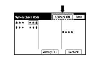
Select "SPCheck ON" from the "System Check Mode" screen and perform speaker check.

OK:

Each speaker outputs sound from the selected audio source properly.


Result:
Result Proceed to
Front No. 1 speaker assembly does not outputs sound A
Rear speaker assembly does not outputs sound B


A

3.CHECK HARNESS AND CONNECTOR (SPEAKER CIRCUIT)

B

6.CHECK HARNESS AND CONNECTOR (SPEAKER CIRCUIT)
3.CHECK HARNESS AND CONNECTOR (SPEAKER CIRCUIT)
a.

Disconnect the I211 radio and display receiver assembly connector.


b.

Disconnect the K1 and L1 front No. 1 speaker assembly connectors.


c.

Measure the resistance according to the value(s) in the table below.

Standard Resistance:
Tester Connection Condition Specified Condition
I211-2 (FL+) - L1-2 Always Below 1 Ω
I211-7 (FL-) - L1-1 Always Below 1 Ω
I211-1 (FR+) - I149-1 (SPI+) Always Below 1 Ω
I211-6 (FR-) - I149-2 (SPI-) Always Below 1 Ω
I149-3 (SPO+) - K1-2 Always Below 1 Ω
I149-4 (SPO-) - K1-1 Always Below 1 Ω
I211-2 (FL+) or L1-2 - Body ground Always 10 kΩ or higher
I211-7 (FL-) or L1-1 - Body ground Always 10 kΩ or higher
I211-1 (FR+) or I149-1 (SPI+) - Body ground Always 10 kΩ or higher
I211-6 (FR-) or I149-2 (SPI-) - Body ground Always 10 kΩ or higher
I149-3 (SPO+) or K1-2 - Body ground Always 10 kΩ or higher
I149-4 (SPO-) or K1-1 - Body ground Always 10 kΩ or higher


Result:
Proceed to
OK
NG


OK

4.INSPECT FRONT NO. 1 SPEAKER ASSEMBLY

NG

REPAIR OR REPLACE HARNESS OR CONNECTOR

4.INSPECT FRONT NO. 1 SPEAKER ASSEMBLY

OK

5.INSPECT TELEMATICS TRANSCEIVER (SPO+,SPO-,SPI+,SPI-)

NG

5.INSPECT TELEMATICS TRANSCEIVER (SPO+,SPO-,SPI+,SPI-)
a.
E418548C53
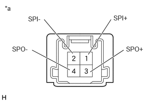
0.948,0.417 1.563,1.146 true 2.385,0.417 1.896,1.167 true 0.688,1.073 1.5,1.5 true 2.656,1.073 1.938,1.542 true 2.438,0.302 2.885,0.521 0.448,0.219 10 false SPI+ 0.604,0.323 1.052,0.542 0.448,0.219 10 false SPI- 2.708,0.969 3.156,1.188 0.448,0.219 10 false SPO+ 0.26,0.969 0.708,1.188 0.448,0.219 10 false SPO- 0.104,0.094 0.552,0.313 0.448,0.219 10 false *a
*a Component without harness connected
(Telematics Transceiver)


Remove the telematics transceiver.

Click hereAudio / Visual / Telematics>TELEMATICS>TELEMATICS TRANSCEIVER>REMOVAL


b.

Measure the resistance according to the value(s) in the table below.


Standard Resistance:
Tester Connection Condition Specified Condition
3 (SPO+) - 1 (SPI+) Always Below 1 Ω
4 (SPO-) - 2 (SPI-) Always Below 1 Ω
1 (SPI+) - 2 (SPI-) Always 10 kΩ or higher
3 (SPO+) - 4 (SPO-) Always 10 kΩ or higher


Result:
Proceed to
OK
NG


OK

NG

6.CHECK HARNESS AND CONNECTOR (SPEAKER CIRCUIT)
a.

Disconnect the I211 radio and display receiver assembly connector.


b.

Disconnect the M4 and N4 rear speaker assembly connectors.


c.

Measure the resistance according to the value(s) in the table below.

Standard Resistance:
Tester Connection Condition Specified Condition
I211-3 (RL+) - N4-2 Always Below 1 Ω
I211-8 (RL-) - N4-1 Always Below 1 Ω
I211-4 (RR+) - M4-2 Always Below 1 Ω
I211-9 (RR-) - M4-1 Always Below 1 Ω
I211-3 (RL+) or N4-2 - Body ground Always 10 kΩ or higher
I211-8 (RL-) or N4-1 - Body ground Always 10 kΩ or higher
I211-4 (RR+) or M4-2 - Body ground Always 10 kΩ or higher
I211-9 (RR-) or M4-1 - Body ground Always 10 kΩ or higher


Result:
Proceed to
OK
NG


OK

7.INSPECT REAR SPEAKER ASSEMBLY

NG

REPAIR OR REPLACE HARNESS OR CONNECTOR

8.CHECK SPEAKER (OPERATION CHECK)

b.

Select "Failure Diagnosis" from the "Service Menu" screen.


c.

Select "System Check" from the "Failure Diagnosis" screen.


d.

Select "SPCheck ON" from the "System Check Mode" screen and perform speaker check.

OK:

Each speaker outputs sound from the selected audio source properly.


Result:
Result Proceed to
Front No. 1 speaker assembly or front No. 2 speaker assembly does not outputs sound A
Rear speaker assembly does not outputs sound B


A

9.CHECK HARNESS AND CONNECTOR (SPEAKER CIRCUIT)

B

13.CHECK HARNESS AND CONNECTOR (SPEAKER CIRCUIT)
9.CHECK HARNESS AND CONNECTOR (SPEAKER CIRCUIT)
a.

Disconnect the I211 radio and display receiver assembly connector.


b.

Disconnect the K1 and L1 front No. 1 speaker assembly connectors.


c.

Disconnect the I76 and I77 front No. 2 speaker assembly connectors.


d.

Disconnect the I149 telematics transceiver connector.


e.

Measure the resistance according to the value(s) in the table below.

Standard Resistance:
Tester Connection Condition Specified Condition

*1: for NR Series

*2: except NR Series

I211-2 (FL+) - I77-4 (+*1, TWL+*2) Always Below 1 Ω
I211-7 (FL-) - I77-2 (-*1, TWL-*2) Always Below 1 Ω
I211-1 (FR+) - I149-1 (SPI+) Always Below 1 Ω
I211-6 (FR-) - I149-2 (SPI-) Always Below 1 Ω
I149-3 (SPO+) - I76-4 (+*1, TWR+*2) Always Below 1 Ω
I149-4 (SPO-) - I76-2 (-*1, TWR-*2) Always Below 1 Ω
L1-2 - I77-3 (+) Always Below 1 Ω
L1-1 - I77-1 (-) Always Below 1 Ω
K1-2 - I76-3 (+) Always Below 1 Ω
K1-1 - I76-1 (-) Always Below 1 Ω
I211-2 (FL+) or I77-4 (+*1, TWL+*2) - Body ground Always 10 kΩ or higher
I211-7 (FL-) or I77-2 (-*1, TWL-*2) - Body ground Always 10 kΩ or higher
I211-1 (FR+) or I149-1 (SPI+) - Body ground Always 10 kΩ or higher
I211-6 (FR-) or I149-2 (SPI-) - Body ground Always 10 kΩ or higher
I149-3 (SPO+) or I76-4 (+*1, TWR+*2) - Body ground Always 10 kΩ or higher
I149-4 (SPO-) or I76-2 (-*1, TWR-*2) - Body ground Always 10 kΩ or higher
L1-2 or I77-3 (+) - Body ground Always 10 kΩ or higher
L1-1 or I77-1 (-) - Body ground Always 10 kΩ or higher
K1-2 or I76-3 (+) - Body ground Always 10 kΩ or higher
K1-1 or I76-1 (-) - Body ground Always 10 kΩ or higher


Result:
Proceed to
OK
NG


OK

10.INSPECT FRONT NO. 1 SPEAKER ASSEMBLY

NG

REPAIR OR REPLACE HARNESS OR CONNECTOR

10.INSPECT FRONT NO. 1 SPEAKER ASSEMBLY

OK

11.INSPECT TELEMATICS TRANSCEIVER (SPO+,SPO-,SPI+,SPI-)

NG

11.INSPECT TELEMATICS TRANSCEIVER (SPO+,SPO-,SPI+,SPI-)
a.
E418548C53
0.948,0.417 1.563,1.146 true 2.385,0.417 1.896,1.167 true 0.688,1.073 1.5,1.5 true 2.656,1.073 1.938,1.542 true 2.438,0.302 2.885,0.521 0.448,0.219 10 false SPI+ 0.604,0.323 1.052,0.542 0.448,0.219 10 false SPI- 2.708,0.969 3.156,1.188 0.448,0.219 10 false SPO+ 0.26,0.969 0.708,1.188 0.448,0.219 10 false SPO- 0.104,0.094 0.552,0.313 0.448,0.219 10 false *a
*a Component without harness connected
(Telematics Transceiver)


Remove the telematics transceiver.

Click hereAudio / Visual / Telematics>TELEMATICS>TELEMATICS TRANSCEIVER>REMOVAL


b.

Measure the resistance according to the value(s) in the table below.


Standard Resistance:
Tester Connection Condition Specified Condition
3 (SPO+) - 1 (SPI+) Always Below 1 Ω
4 (SPO-) - 2 (SPI-) Always Below 1 Ω
1 (SPI+) - 2 (SPI-) Always 10 kΩ or higher
3 (SPO+) - 4 (SPO-) Always 10 kΩ or higher


Result:
Proceed to
OK
NG


OK

12.REPLACE FRONT NO. 2 SPEAKER ASSEMBLY

NG

12.REPLACE FRONT NO. 2 SPEAKER ASSEMBLY
a.

b.

Check if the malfunction disappears.


Result:
Result Proceed to
Malfunction disappears A
Malfunction occurs B


A

END (FRONT NO. 2 SPEAKER ASSEMBLY IS DEFECTIVE)

B

13.CHECK HARNESS AND CONNECTOR (SPEAKER CIRCUIT)
a.

Disconnect the I211 radio and display receiver assembly connector.


b.

Disconnect the M4 and N4 rear speaker assembly connectors.


c.

Measure the resistance according to the value(s) in the table below.

Standard Resistance:
Tester Connection Condition Specified Condition
I211-3 (RL+) - N4-2 Always Below 1 Ω
I211-8 (RL-) - N4-1 Always Below 1 Ω
I211-4 (RR+) - M4-2 Always Below 1 Ω
I211-9 (RR-) - M4-1 Always Below 1 Ω
I211-3 (RL+) or N4-2 - Body ground Always 10 kΩ or higher
I211-8 (RL-) or N4-1 - Body ground Always 10 kΩ or higher
I211-4 (RR+) or M4-2 - Body ground Always 10 kΩ or higher
I211-9 (RR-) or M4-1 - Body ground Always 10 kΩ or higher


Result:
Proceed to
OK
NG


OK

14.INSPECT REAR SPEAKER ASSEMBLY

NG

REPAIR OR REPLACE HARNESS OR CONNECTOR