STEERING COLUMN STEERING COLUMN ASSEMBLY REMOVAL
CAUTION / NOTICE / HINT
The necessary procedures (adjustment, calibration, initialization, or registration) that must be performed after parts are removed and installed, or replaced during electric power steering column sub-assembly removal/installation are shown below.
| Replaced Part or Performed Procedure | Necessary Procedure | Effect/Inoperative Function when Necessary Procedure not Performed | Link |
|---|---|---|---|
|
*1: If matchmarks were not placed when removing parts related to steering operation, perform end position initial setting. |
|||
| Power steering ECU assembly | Update ECU security key | Vehicle Control History (RoB) are stored | ( 202304,999999,_V1,_143216,_0598316,RM100000002B3ML,) 202304,999999,_V1,_143216,_0598316,RM100000002B3ML,)
|
| ECU configuration | ·
Vehicle Control History (RoB) are stored ·
EPS warning light illuminates |
(202304,999999,_V1,_143216,_0598316,RM100000002B3MK,)
|
|
| Perform power steering ECU initial setting (assist map writing) | ·
Vehicle Control History (RoB) are stored ·
EPS warning light illuminates |
(202304,202307,_55,_080761,_0392075,RM100000002B8OH,202307,999999,_55,_080761,_0392075,RM100000002CNVO,)
|
|
| End position initial setting | - | ||
| Electric power steering column sub-assembly | Perform power steering ECU initial setting (assist map writing) | ·
Vehicle Control History (RoB) are stored ·
EPS warning light illuminates |
(202304,202307,_55,_080761,_0392075,RM100000002B8OH,202307,999999,_55,_080761,_0392075,RM100000002CNVO,)
|
| End position initial setting | - | ||
| No. 2 steering intermediate shaft assembly*1 | End position initial setting | - | (202304,202307,_55,_080761,_0392075,RM100000002B8OH,202307,999999,_55,_080761,_0392075,RM100000002CNVO,)
|
| Replaced Part or Performed Procedure | Necessary Procedure | Effect/Inoperative Function when Necessary Procedure not Performed | Link |
|---|---|---|---|
|
*1: If matchmarks were not placed when removing parts related to steering operation, perform end position initial setting. |
|||
| Power steering ECU assembly | except NR Series
Update ECU security key |
Vehicle Control History (RoB) are stored | (202304,999999,_V1,_143216,_0598316,RM100000002B3ML,)
|
except NR Series
ECU configuration |
·
Vehicle Control History (RoB) are stored ·
EPS warning light illuminates |
(202304,999999,_V1,_143216,_0598316,RM100000002B3MK,)
|
|
except NR Series
Perform power steering ECU initial setting (assist map writing) |
·
Vehicle Control History (RoB) are stored ·
EPS warning light illuminates |
(202304,999999,_55,_080761,_0392052,RM100000002B8PZ,)
|
|
except NR Series
End position initial setting |
- | (202304,999999,_55,_080761,_0392052,RM100000002B8PZ,)
|
|
for NR Series
Perform power steering ECU initial setting (torque sensor zero point calibration and assist map writing) |
·
Vehicle Control History (RoB) are stored ·
Steering effort different between turning steering wheel left and right ·
EPS warning light illuminates |
(202304,999999,_55,_080761,_0392052,RM100000002B8PZ,)
|
|
| Electric power steering column sub-assembly | for NR Series
Perform power steering ECU initial setting (torque sensor zero point calibration and assist map writing) |
·
Vehicle Control History (RoB) are stored ·
Steering effort different between turning steering wheel left and right ·
EPS warning light illuminates |
(202304,999999,_55,_080761,_0392052,RM100000002B8PZ,)
|
except NR Series
Perform power steering ECU initial setting (assist map writing) |
·
Vehicle Control History (RoB) are stored ·
EPS warning light illuminates |
(202304,999999,_55,_080761,_0392052,RM100000002B8PZ,)
|
|
except NR Series
End position initial setting |
- | (202304,999999,_55,_080761,_0392052,RM100000002B8PZ,)
|
|
except NR Series
No. 2 steering intermediate shaft assembly*1 |
End position initial setting | - | (202304,999999,_55,_080761,_0392052,RM100000002B8PZ,)
|
CAUTION / NOTICE / HINT
- NOTICE:
-
After turning the ignition switch (for Gasoline Model) or power switch (for HV Model) off, waiting time may be required before disconnecting the cable from the negative (-) auxiliary battery terminal. Therefore, make sure to read the disconnecting the cable from the negative (-) auxiliary battery terminal notices before proceeding with work.
- HINT:
-
When the cable is disconnected / reconnected to the battery terminal, systems temporarily stop operating. However, each system has a function that completes learning the first time the system is used.
Learning completes when vehicle is driven (for HV Model) Effect/Inoperative Function when Necessary Procedure not Performed Necessary Procedures Link Front Camera System Drive the vehicle straight ahead at 15 km/h (9 mph) or more for 1 second or more. ( 202304,999999,_95,_139716,_0584193,RM1000000029F4C,)
Learning completes when vehicle is driven (for Gasoline Model) Effect/Inoperative Function when Necessary Procedure not Performed Necessary Procedures Link Stop and Start System Idle the engine for approximately 5 to 60 minutes or drive the vehicle until stop and start control is permitted ( 201906,999999,_51,_080774,_0393362,RM100000001HXHC,)
Pre-collision System Perform steering sensor zero point calibration ( 202304,999999,_95,_139716,_0601175,RM100000002BFOE,)
Lane Tracing Assist System Front Camera System Drive the vehicle straight ahead at 15 km/h (9 mph) or more for 1 second or more. ( 202304,999999,_95,_139716,_0584193,RM1000000029F4C,)
PROCEDURE

 1. PRECAUTION
2. ALIGN FRONT WHEELS FACING STRAIGHT AHEAD
45130
3.REMOVE HORN BUTTON ASSEMBLY
4.REMOVE STEERING WHEEL ASSEMBLY
45287
5.REMOVE LOWER STEERING COLUMN COVER
- NOTICE:
-
Removing the lower steering column cover in the incorrect order will cause the parts to break.
Release the tilt and telescopic lever and fully extend and lower the steering column assembly.
Lock the tilt and telescopic lever.
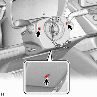
Remove the 3 screws.
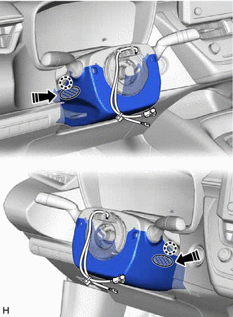

|
Push Area |

|
Push in this direction |
While pressing the push area shown in the illustration to disengage the 2 claws, slightly lower the lower steering column cover.
45286B
6.REMOVE UPPER STEERING COLUMN COVER
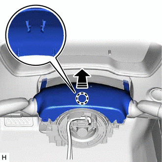
|
|
Separate in this direction |
Disengage the claw and separate the upper steering column cover.
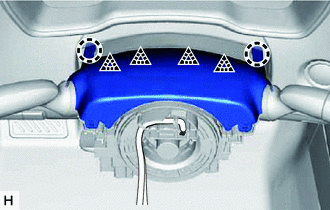
Disengage the 2 claws and 4 clips to remove the upper steering column cover.
89782
7.REMOVE TRANSPONDER KEY COIL (w/o Smart Entry and Start System)
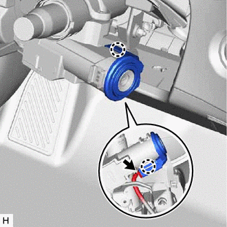
Disconnect the connector.
Disengage the 2 claws and remove the transponder key coil.
8.REMOVE TURN SIGNAL SWITCH ASSEMBLY WITH SPIRAL CABLE SUB-ASSEMBLY
- NOTICE:
- ·
Do not remove/install the spiral cable with sensor sub-assembly with the auxiliary battery connected and the ignition switch (for Gasoline Model) or power switch (for HV Model) on (IG).
·Do not rotate the spiral cable with sensor sub-assembly without the steering wheel assembly installed, with the auxiliary battery connected and the ignition switch (for Gasoline Model) or power switch (for HV Model) on (IG).
·Ensure that the steering wheel assembly is installed and aligned straight when inspecting the steering sensor.
Disconnect each connector from the turn signal switch assembly with spiral cable sub-assembly.
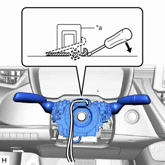
| *a | Clamp |
Using pliers, expand the clamp.
While holding the clamp expanded, raise the claw using a screwdriver to disengage it, and then remove the turn signal switch assembly with spiral cable sub-assembly from the steering column assembly.
67914
9.REMOVE FRONT DOOR SCUFF PLATE LH (w/o Knee Airbag)
62112A
10.REMOVE COWL SIDE TRIM SUB-ASSEMBLY LH (w/o Knee Airbag)
55606
11.REMOVE NO. 1 INSTRUMENT PANEL UNDER COVER SUB-ASSEMBLY (w/o Knee Airbag)
55317E
12.REMOVE NO. 1 INSTRUMENT SIDE PANEL (w/o Knee Airbag)
55434F
13.REMOVE LOWER CENTER INSTRUMENT PANEL FINISH PANEL (w/o Knee Airbag)
53601
14.DISCONNECT HOOD LOCK CONTROL LEVER SUB-ASSEMBLY (w/o Knee Airbag)
55432B
15.REMOVE LOWER INSTRUMENT PANEL FINISH PANEL (w/o Knee Airbag)
73900
16.REMOVE LOWER NO. 1 INSTRUMENT PANEL AIRBAG ASSEMBLY (w/ Knee Airbag)
58816D
17.REMOVE FRONT NO. 1 CONSOLE BOX INSERT
58831A
18.REMOVE FRONT CONSOLE UPPER PANEL GARNISH
87211
19.REMOVE NO. 1 AIR DUCT
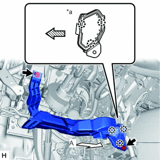
| *a | View A |

|
Front |
Remove the 2 bolts.
Disengage the 3 claws to remove the No. 1 air duct.
- NOTICE:
-
Be careful not to deform or damage the lower heater case of the air conditioner unit assembly when removing the No. 1 air duct.
45259A
20.REMOVE COLUMN HOLE COVER SILENCER SHEET
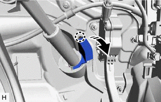
|
|
Open in this direction |
Disengage the claw and open the column hole cover silencer sheet.
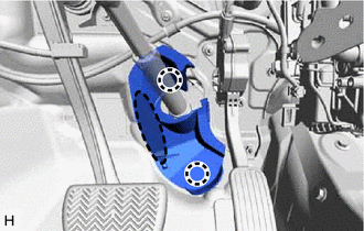

|
Place Hand Here |
Disengage the 2 claws to remove the column hole cover silencer sheet.
45260
21.SEPARATE NO. 2 STEERING INTERMEDIATE SHAFT ASSEMBLY
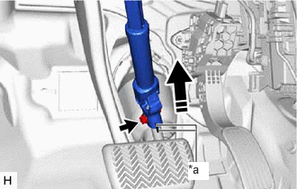
| *a | Matchmark |
|
|
Separate in this direction |
Put matchmarks on the No. 2 steering intermediate shaft assembly and steering gear assembly.
Remove the bolt.
Separate the No. 2 steering intermediate shaft assembly from the steering gear assembly.
45260
22.REMOVE NO. 2 STEERING INTERMEDIATE SHAFT ASSEMBLY

| *a | Matchmark |
|
|
Remove in this direction |
Put matchmarks on the No. 2 steering intermediate shaft assembly and steering column assembly.
Remove the bolt.
Remove the No. 2 steering intermediate shaft assembly from the steering column assembly.
84340
23.REMOVE STOP LIGHT SWITCH ASSEMBLY
24.REMOVE STEERING COLUMN ASSEMBLY
Disconnect each connector and disengage each wire harness clamp from the steering column assembly.
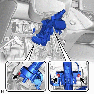
Remove the bolt, 2 nuts and steering column assembly.