NR Series ENGINE MECHANICAL CAMSHAFT REMOVAL
CAUTION / NOTICE / HINT
The necessary procedures (adjustment, calibration, initialization or registration) that must be performed after parts are removed and installed, or replaced during camshaft removal/installation are shown below.
| Replaced Part or Performed Procedure | Necessary Procedure | Effect/Inoperative Function when Necessary Procedure not Performed | Link |
|---|---|---|---|
| Replacement of ECM | Perform Vehicle Identification Number (VIN) or frame number registration | DTC is stored | ( 201906,999999,_51,_080777,_0393969,RM100000001I1RD,) 201906,999999,_51,_080777,_0393969,RM100000001I1RD,)
|
1.
Reset memory 2.
Deceleration sensor zero point calibration 3.
CVT oil pressure calibration |
·
Large shift shock ·
Deterioration of fuel efficiency |
(201906,999999,_52,_080728,_0392261,RM100000001HP98,)
|
|
| Code registration (Immobiliser system) | Engine start | See Service Bulletin for the registration method | |
| Replacement of piston ring | Clear Heavy Knock History | - | (201906,999999,_51,_080777,_0393969,RM100000001I1RE,)
|
·
Replacement of engine assembly ·
Gas leaks from exhaust system ·
Replacement of camshaft (for intake or exhaust camshaft) ·
Replacement of camshaft timing gear assembly ·
Replacement of camshaft timing exhaust gear assembly |
Inspection After Repair | ·
Poor idle, etc. ·
Engine start function, etc. |
(201906,999999,_51,_080777,_0393969,RM100000001I1RE,)
|
| Replacement of starter assembly | Clear the number of starter operations | Stop and Start System | (201906,999999,_51,_080774,_0393362,RM100000001HXHH,)
|
| Replacement of battery | Integrated current value initialization | ||
| Replacement of continuously variable transaxle assembly | Air bleed the oil pump with motor assembly | Stop and Start System | (201906,999999,_51,_080774,_0393362,RM100000001HXHH,)
|
1.
Reset memory 2.
Deceleration sensor zero point calibration 3.
CVT oil pressure calibration |
·
Large shift shock ·
Deterioration of fuel efficiency |
(201906,999999,_52,_080728,_0392261,RM100000001HP98,)
|
|
| Replacement of CVT fluid | Air bleed the oil pump with motor assembly | Stop and Start System | (201906,999999,_51,_080774,_0393362,RM100000001HXHH,)
|
| ATF thermal degradation estimate reset | The value of the Data List item "ATF Thermal Degradation Estimate" is not estimated correctly | (201906,999999,_52,_080728,_0392261,RM100000001HP98,)
|
|
| Tires | Rear television camera assembly optical axis (Back camera position setting) | Parking Assist Monitor System | (202304,999999,_56,_080754,_0596561,RM100000002AX0C,)
|
| Suspension parts | Rear television camera assembly optical axis (Back camera position setting) | Parking Assist Monitor System | (202304,999999,_56,_080754,_0596561,RM100000002AX0C,)
|
| Front wheel alignment adjustment | ·
Perform "Reset Memory" ·
Perform acceleration sensor zero point calibration and store system information memorization |
·
VSC is disabled or malfunctions ·
DTCs are stored ·
Slip indicator light illuminates ·
ABS warning light illuminates |
(202304,999999,_54,_080770,_0599814,RM100000002BA8F,)
|
- HINT:
-
When the cable is disconnected / reconnected to the battery terminal, systems temporarily stop operating. However, each system has a function that completes learning the first time the system is used.
Learning completes when vehicle is driven Effect/Inoperative Function when Necessary Procedure not Performed Necessary Procedure Link Stop and Start System Idle the engine for approximately 5 to 60 minutes or drive the vehicle until stop and start control is permitted ( 201906,999999,_51,_080774,_0393362,RM100000001HXHC,)
Pre-collision System Perform steering sensor zero point calibration ( 202304,999999,_95,_139716,_0601175,RM100000002BFOE,)
Lane Tracing Assist System
PROCEDURE

 1.INSTALL ENGINE ASSEMBLY TO ENGINE STAND
2.REMOVE ENGINE HANGERS
17201
3.REMOVE TURBOCHARGER SUB-ASSEMBLY
23250
4.REMOVE FUEL INJECTOR ASSEMBLY
23100X
5.REMOVE FUEL (ENGINE ROOM SIDE) PUMP ASSEMBLY
19500D
6.REMOVE NO. 1 IGNITION COIL
23818
7.REMOVE FUEL VAPOR FEED PIPE
16206
8.REMOVE WATER BY-PASS PIPE SUB-ASSEMBLY
11452
9.REMOVE ENGINE OIL LEVEL DIPSTICK GUIDE
29300
10.REMOVE VACUUM PUMP ASSEMBLY
15370
11.REMOVE CAMSHAFT TIMING OIL CONTROL SOLENOID ASSEMBLY (for Intake Side)
15370
12.REMOVE CAMSHAFT TIMING OIL CONTROL SOLENOID ASSEMBLY (for Exhaust Side)
11201
13.REMOVE CYLINDER HEAD COVER SUB-ASSEMBLY
11213
14.REMOVE CYLINDER HEAD COVER GASKET
11191A
15.REMOVE SPARK PLUG TUBE GASKET
16.SET NO. 1 CYLINDER TO TDC/COMPRESSION
13470
17.REMOVE CRANKSHAFT PULLEY ASSEMBLY
12315A
18.REMOVE ENGINE MOUNTING BRACKET RH
11310
19.REMOVE TIMING CHAIN COVER ASSEMBLY
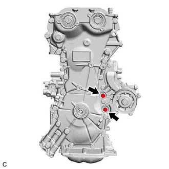
Remove the 2 bolts from the engine water pump assembly.
Remove the timing chain cover assembly.
11302A
20.REMOVE TIMING CHAIN COVER OIL SEAL
16322
21.REMOVE WATER INLET PIPE
13540
22.REMOVE NO. 1 CHAIN TENSIONER ASSEMBLY
13559
23.REMOVE CHAIN TENSIONER SLIPPER
13566B
24.REMOVE TIMING CHAIN GUIDE
13506
25.REMOVE CHAIN SUB-ASSEMBLY
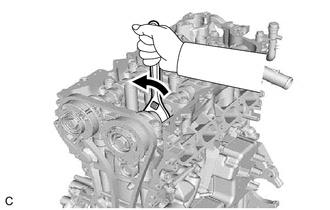
Hold the hexagonal portion of the camshaft with a wrench and turn the camshaft timing gear assembly counterclockwise to loosen the chain sub-assembly between the camshaft timing exhaust gear assembly and camshaft timing gear assembly.
With the chain sub-assembly loosened, release the chain sub-assembly from the camshaft timing gear assembly and place it on the camshaft timing gear assembly.
- NOTICE:
-
Be sure to release the chain sub-assembly from the sprocket completely.
Turn the camshaft clockwise to return it to its original position and remove the chain sub-assembly.
13050
26.REMOVE CAMSHAFT TIMING GEAR ASSEMBLY
13070A
27.REMOVE CAMSHAFT TIMING EXHAUST GEAR ASSEMBLY
28.REMOVE CAMSHAFT BEARING CAP
13511
29.REMOVE CAMSHAFT
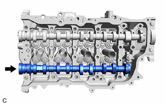
Remove the camshaft from the camshaft housing sub-assembly.
13512
30.REMOVE NO. 2 CAMSHAFT
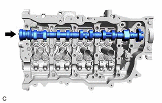
Remove the No. 2 camshaft from the camshaft housing sub-assembly.
15678A
31.REMOVE OIL CONTROL VALVE FILTER
16671
32.REMOVE WATER VALVE
11103
33.REMOVE CAMSHAFT HOUSING SUB-ASSEMBLY
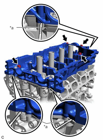
| *a | Protective Tape |
Remove the 4 bolts from the camshaft housing sub-assembly.
Remove the camshaft housing sub-assembly by prying between the cylinder head sub-assembly and camshaft housing sub-assembly with a screwdriver with its tip wrapped with protective tape.
- NOTICE:
-
Be careful not to damage the contact surfaces of the cylinder head sub-assembly and camshaft housing sub-assembly.