K313 CVT TRANSMISSION CONTROL CABLE(for TFTM Made) INSTALLATION
PROCEDURE

 33820B
1.INSTALL TRANSMISSION CONTROL CABLE ASSEMBLY
33820B
1.INSTALL TRANSMISSION CONTROL CABLE ASSEMBLY
Pass the transmission control cable assembly into the vehicle and install the transmission control cable assembly to the vehicle body with the 2 nuts.
- Torque:
- 6.0 N*m (61 kgf*cm, 53 in.*lbf)
Engage the guide to connect the transmission control cable assembly to the vehicle body.
Install the nut.
- Torque:
- 6.0 N*m (61 kgf*cm, 53 in.*lbf)
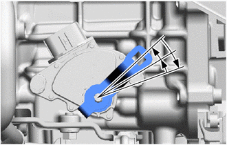
Turn the transmission control shaft lever clockwise until it stops, and then from that position turn it counterclockwise by 2 notches to set it to the N position.
Connect the transmission control cable assembly to the No. 1 transmission control cable bracket with a new clip.
Connect the transmission control cable assembly to the transmission control shaft lever with the nut.
- Torque:
- 12 N*m (122 kgf*cm, 9 ft.*lbf)
Push the 2 claws together at the top of the lock piece. While holding the 2 claws together, push the 2 lugs on the bottom of the lock piece toward each other and upward to push up the lock piece.
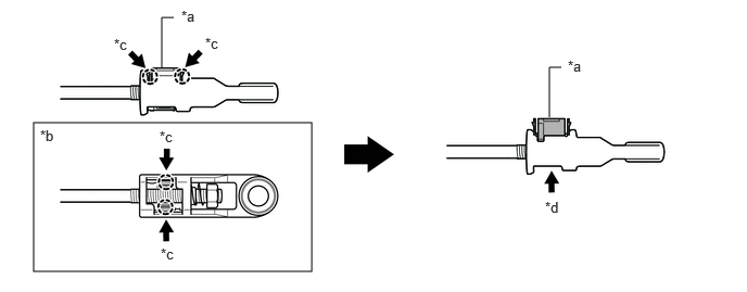
| *a | Lock Piece | *b | Bottom View |
| *c | Push | *d | Push up |
Turn the nut of the transmission control cable assembly approximately 180° counterclockwise. While holding the nut in place, push in the stopper until it clicks twice.
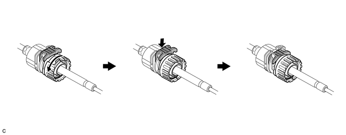
| *a | Stopper | *b | Nut |
| *c | Push in | *d | Turn approximately 180° |
- HINT:
-
If the stopper cannot be pushed in, slightly turn the nut clockwise and then push in the stopper again.
Connect the transmission control cable assembly to the transmission floor shift assembly. Check that the spring is positioned at (A) and push in the stopper.
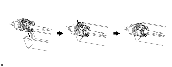
| *1 | Transmission Floor Shift Assembly | - | - |
| *a | Stopper | *b | Spring |
| *c | Nut | *d | Push in |
- NOTICE:
- ·
If the stopper cannot be pushed in, slightly turn the nut clockwise and then push in the stopper again.
·Make sure that the transmission control cable assembly is securely locked.
·Do not forcibly pull the transmission control cable assembly into the cabin.
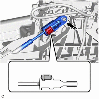
| *a | Lock Piece |

|
Connect in this Direction |
Confirm that the shift lever is in N, and then connect the end of the transmission control cable assembly to the transmission floor shift assembly.
- NOTICE:
- ·
Securely connect the end of the transmission control cable assembly to the transmission floor shift assembly.
·Connect the end of the transmission control cable assembly so that its adjustment lock section is on the driver side.
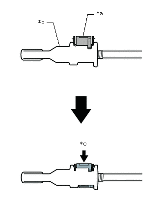
| *a | Lock Piece |
| *b | Adjuster Case |
| *c | Push in |
Push the lock piece into the adjuster case.
- NOTICE:
- ·
Check that the park/neutral position switch assembly and shift lever are in N.
·Securely push in the lock piece until the 2 claws are engaged.
·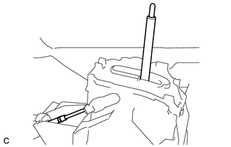 1.76,0.354 2.177,0.354 false 0.51,1.167 0.656,1.167 0.656,1.167 1.094,1.677 true 0.323,1.094 0.552,1.292 0.229,0.198 10 false *1 1.563,0.26 1.813,0.469 0.25,0.208 10 false *a
*1 Transmission Control Cable Assembly *a Lever Shaft
When pushing in the lock piece of the adjuster case to lock it, remove your hand from the lever shaft.
·When pushing in the lock piece of the adjuster case to lock it, do not move the lever shaft or transmission control cable assembly forward or backward.
58861B
2.INSTALL NO. 1 CONSOLE BOX DUCT (w/ Rear Air Duct)
58862B
3.INSTALL NO. 2 CONSOLE BOX DUCT (w/ Rear Air Duct)
58810J
4.INSTALL CONSOLE BOX ASSEMBLY
58151
5.INSTALL FRONT NO. 1 FLOOR HEAT INSULATOR
Install the front No. 1 floor heat insulator to the vehicle body with the 3 nuts.
- Torque:
- 5.0 N*m (51 kgf*cm, 44 in.*lbf)
17410
6.INSTALL FRONT EXHAUST PIPE ASSEMBLY (TWC: Rear Catalyst)
57533B
7.INSTALL FRONT FLOOR CENTER BRACE
58166A
8.INSTALL FRONT FLOOR COVER LH
58165C
9.INSTALL FRONT FLOOR COVER RH
74404A
10.INSTALL BATTERY CLAMP SUB-ASSEMBLY
11.CONNECT ENGINE WIRE
12.INSTALL BATTERY
89661
13.INSTALL ECM
17701
14.INSTALL AIR CLEANER CASE SUB-ASSEMBLY
17705
15.INSTALL AIR CLEANER CAP WITH AIR CLEANER HOSE
17751
16.INSTALL INLET NO. 1 AIR CLEANER
53289A
17.INSTALL RADIATOR SUPPORT OPENING COVER
18.CONNECT CABLE TO NEGATIVE BATTERY TERMINAL
19.INSPECT SHIFT LEVER POSITION
20.ADJUST SHIFT LEVER POSITION
21.INSPECT FOR EXHAUST GAS LEAK
- HINT:
-
Perform "Inspection After Repairs" after repairing or replacing the exhaust system.
22. INITIALIZATION AFTER RECONNECTING BATTERY TERMINAL
- HINT:
-
When disconnecting and reconnecting the battery, there is an automatic learning function that completes learning when the respective system is used.