INTERIOR PANELS / TRIM FRONT CONSOLE BOX INSTALLATION
PROCEDURE

 55620F
1.INSTALL CONSOLE BOX CUP HOLDER ASSEMBLY
55620F
1.INSTALL CONSOLE BOX CUP HOLDER ASSEMBLY
- HINT:
-
Perform this procedure only when replacement of the console box cup holder assembly.
Install the console box cup holder assembly with the 8 screws.
Install the electric parking brake switch assembly.
w/ Illumination:
Install the instrument panel under tray wall retainer.
2.INSTALL CONSOLE BOX ASSEMBLY


|
Install in this Direction |
Engage the 3 guides as shown in the illustration.
Install console box assembly with the 4 bolts and 2 screws.
Engage the clamp.
3.INSTALL BLE INDOOR DIGITAL KEY RECEIVER ASSEMBLY (w/ Digital Key System)
58815C
4.INSTALL CONSOLE BOX CARPET
Install the console box carpet.
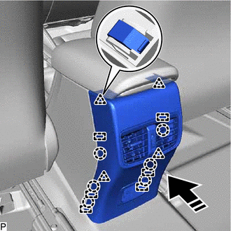
5.INSTALL CONSOLE REAR END PANEL SUB-ASSEMBLY
w/ USB Charger:
Connect the connector.
|
|
Install in this Direction |
Engage the 6 guides, 4 clips and 6 claws shown in the illustration to install the console rear end panel sub-assembly.
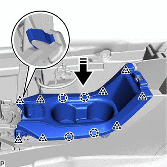
6.INSTALL CONSOLE CUP HOLDER BOX SUB-ASSEMBLY
Engage the clamp.
Connect the 2 connectors.
|
|
Install in this Direction |
Engage the 8 clips and 4 claws as shown in the illustration to install the console cup holder box sub-assembly.
35970F
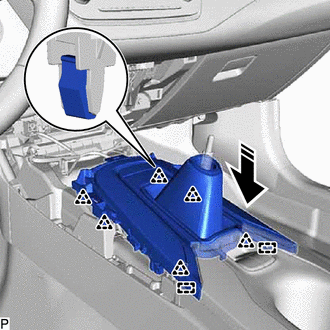
7.INSTALL POSITION INDICATOR HOUSING ASSEMBLY
Connect each connector.
|
|
Install in this Direction |
Engage the 2 guides and 6 clips as shown in the illustration to install the position indicator housing assembly.
33504F
8.INSTALL SHIFT LEVER KNOB SUB-ASSEMBLY (for CVT)
for K313:
for K320 / K321:
for K120 / K121:
33504F
9.INSTALL SHIFT LEVER KNOB SUB-ASSEMBLY (for HV Model)
58831A
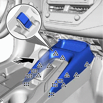
10.INSTALL FRONT CONSOLE UPPER PANEL GARNISH
Engage the clamp.
Connect each connector.
|
|
Install in this Direction |
Engage the 6 guides and 9 clips as shown in the illustration to install the front console upper panel garnish.
58817A
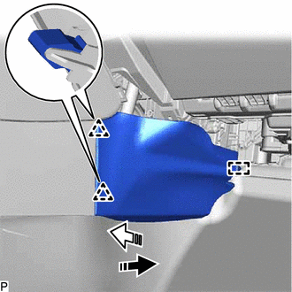
11.INSTALL FRONT NO. 2 CONSOLE BOX INSERT
|
|
Install in this Direction (1) |

|
Install in this Direction (2) |
Engage the guide and 2 clips as shown in the illustration to install the front No. 2 console box insert.
55434F
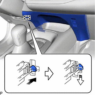
12.INSTALL LOWER CENTER INSTRUMENT PANEL FINISH PANEL
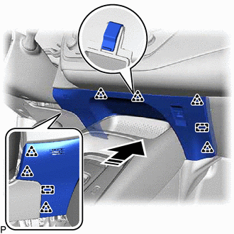
for Type A:
Connect each connector.
|
|
Install in this Direction (1) |
|
|
Install in this Direction (2) |
Engage the hook as shown in the illustration.
|
|
Install in this Direction |
Engage each guide and 7 clips as shown in the illustration to install the lower center instrument panel finish panel.
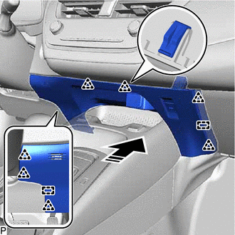
for Type B:
Connect each connector and engage the clamp.
|
|
Install in this Direction |
Engage each guide and 7 clips as shown in the illustration to install the lower center instrument panel finish panel.
58816D
13.INSTALL FRONT NO. 1 CONSOLE BOX INSERT

|
|
Install in this Direction (1) |
|
|
Install in this Direction (2) |
Engage the guide and 3 clips as shown in the illustration to install the front No. 1 console box insert.
55606
14.INSTALL NO. 1 INSTRUMENT PANEL UNDER COVER SUB-ASSEMBLY
w/ Illumination:
Connect the connector.
Engage the clamp.
Engage the 2 claws to connect the DLC3.
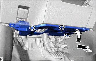
|
|
Install in this Direction (1) |
|
|
Install in this Direction (2) |
Engage the guide and 2 claws as shown in the illustration.
Install the No. 1 instrument panel under cover sub-assembly with the 2 screws.