NR Series ENGINE CONTROL CAMSHAFT OIL CONTROL SOLENOID REMOVAL
CAUTION / NOTICE / HINT
The necessary procedures (adjustment, calibration, initialization or registration) that must be performed after parts are removed and installed, or replaced during camshaft timing oil control solenoid assembly removal/installation are shown below.
| Replaced Part or Performed Procedure | Necessary Procedure | Effect/Inoperative Function when Necessary Procedure not Performed | Link |
|---|---|---|---|
| Replacement of ECM | Perform Vehicle Identification Number (VIN) or frame number registration | DTC is stored | ( 201906,999999,_51,_080777,_0393969,RM100000001I1RD,) 201906,999999,_51,_080777,_0393969,RM100000001I1RD,)
|
1.
Reset memory 2.
Deceleration sensor zero point calibration 3.
CVT oil pressure calibration |
·
Large shift shock ·
Deterioration of fuel efficiency |
(201906,999999,_52,_080728,_0392261,RM100000001HP98,)
|
|
| Code registration (Immobiliser system) | Engine start | See Service Bulletin for the registration method | |
| Gas leaks from exhaust system | Inspection After Repair | ·
Poor idle, etc. ·
Engine start function, etc. |
(201906,999999,_51,_080777,_0393969,RM100000001I1RE,)
|
| Replacement of battery | Integrated current value initialization | Stop and Start System | (201906,999999,_51,_080774,_0393362,RM100000001HXHH,)
|
| Replacement of CVT fluid | Air bleed the oil pump with motor assembly | ||
| ATF thermal degradation estimate reset | The value of the Data List item "ATF thermal Degradation Estimate" is not estimated correctly | (201906,999999,_52,_080728,_0392261,RM100000001HP98,)
|
|
| Suspension parts | Rear television camera assembly optical axis (Back camera position setting) | Parking Assist Monitor System | (202304,999999,_56,_080754,_0596561,RM100000002AX0C,)
|
| Front wheel alignment adjustment | ·
Perform "Reset Memory" ·
Perform acceleration sensor zero point calibration and store system information memorization |
·
VSC is disabled or malfunctions ·
DTCs are stored ·
Slip indicator light illuminates ·
ABS warning light illuminates |
(202304,999999,_54,_080770,_0599814,RM100000002BA8F,)
|
- HINT:
-
When the cable is disconnected / reconnected to the battery terminal, systems temporarily stop operating. However, each system has a function that completes learning the first time the system is used.
Learning completes when vehicle is driven Effect/Inoperative Function when Necessary Procedure not Performed Necessary Procedure Link Stop and Start System Idle the engine for approximately 5 to 60 minutes or drive the vehicle until stop and start control is permitted ( 201906,999999,_51,_080774,_0393362,RM100000001HXHC,)
Pre-collision System Perform steering sensor zero point calibration ( 202304,999999,_95,_139716,_0601175,RM100000002BFOE,)
Lane Tracing Assist System
PROCEDURE

 1. PRECAUTION
- NOTICE:
-
After turning the ignition switch off, waiting time may be required before disconnecting the cable from the negative (-) battery terminal.
15370
2.REMOVE CAMSHAFT TIMING OIL CONTROL SOLENOID ASSEMBLY (for Exhaust Side)
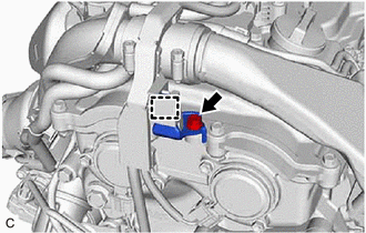
Remove the bolt and separate the engine wire from the cylinder head cover sub-assembly.
Disengage the clamp to remove the wire harness clamp bracket from the engine wire.

Disconnect the camshaft timing oil control solenoid assembly connector.
Remove the 2 bolts and camshaft timing oil control solenoid assembly from the timing chain cover assembly.
- NOTICE:
-
If the camshaft timing oil control solenoid assembly has been struck or dropped, replace it.
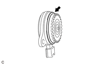
Remove the O-ring from the camshaft timing oil control solenoid assembly.
- NOTICE:
- ·
If the O-ring comes off in the timing chain cover assembly, make sure to remove it.
·Do not drop the O-ring into the timing chain cover assembly.
3.REMOVE ENGINE ASSEMBLY WITH TRANSAXLE (When Not Using the Engine Support Bridge)
4.DISCONNECT CABLE FROM NEGATIVE BATTERY TERMINAL (When Using the Engine Support Bridge)
51410
5.REMOVE NO. 1 ENGINE UNDER COVER ASSEMBLY (When Using the Engine Support Bridge)
51443C
6.REMOVE REAR ENGINE UNDER COVER RH (When Using the Engine Support Bridge)
7.REMOVE WINDSHIELD WIPER MOTOR AND LINK ASSEMBLY (When Using the Engine Support Bridge)
55737B
8.REMOVE NO. 1 HEATER AIR DUCT SPLASH SHIELD SEAL (When Using the Engine Support Bridge)
w/ No. 1 Heater Air Duct Splash Shield Seal
55701J
9.REMOVE OUTER COWL TOP PANEL SUB-ASSEMBLY (When Using the Engine Support Bridge)
53289A
10.REMOVE RADIATOR SUPPORT OPENING COVER (When Using the Engine Support Bridge)
17751
11.REMOVE INLET NO. 1 AIR CLEANER (When Using the Engine Support Bridge)
17705
12.REMOVE AIR CLEANER CAP WITH AIR CLEANER HOSE (When Using the Engine Support Bridge)
17701
13.REMOVE AIR CLEANER CASE SUB-ASSEMBLY (When Using the Engine Support Bridge)
89661
14.REMOVE ECM (When Using the Engine Support Bridge)
15.REMOVE BATTERY (When Using the Engine Support Bridge)
16.DISCONNECT ENGINE WIRE (When Using the Engine Support Bridge)
74404A
17.REMOVE BATTERY CLAMP SUB-ASSEMBLY (When Using the Engine Support Bridge)
18.REMOVE WIRE HARNESS CLAMP BRACKET (When Using the Engine Support Bridge)
82286A
19.DISCONNECT NO. 2 EARTH WIRE (When Using the Engine Support Bridge)
20.INSTALL ENGINE HANGERS (When Using the Engine Support Bridge)
21.INSTALL ENGINE SUPPORT BRIDGE (When Using the Engine Support Bridge)
12305
22.REMOVE ENGINE MOUNTING INSULATOR SUB-ASSEMBLY RH (When Using the Engine Support Bridge)
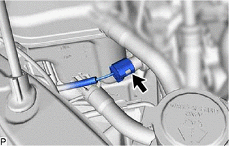
Disconnect the air conditioner pressure sensor connector.
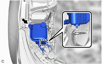
Remove the bolt.
Disengage the pin and separate the reserve sealed tank.
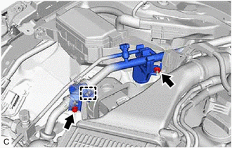
Remove the bolt and disengage the clamp to remove the No. 1 cooler refrigerant hose bracket from the engine mounting insulator sub-assembly RH.
Remove the nut to separate the No. 2 cooler refrigerant hose bracket from the vehicle body.
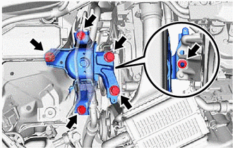
Remove the 4 bolts, 2 nuts and engine mounting insulator sub-assembly RH from the vehicle body and engine mounting bracket RH.
- HINT:
-
As the engine mounting insulator sub-assembly RH contacts the air conditioning tube assembly and cannot be taken out, move the engine mounting insulator sub-assembly RH to a position where the bolt of the camshaft timing oil control solenoid assembly can be removed.
15370
23.REMOVE CAMSHAFT TIMING OIL CONTROL SOLENOID ASSEMBLY (for Intake Side)
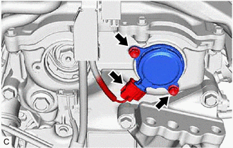
Disconnect the camshaft timing oil control solenoid assembly connector.
Remove the 2 bolts and camshaft timing oil control solenoid assembly from the timing chain cover assembly.
- NOTICE:
-
If the camshaft timing oil control solenoid assembly has been struck or dropped, replace it.
Remove the O-ring from the camshaft timing oil control solenoid assembly.
- NOTICE:
- ·
If the O-ring comes off in the timing chain cover assembly, make sure to remove it.
·Do not drop the O-ring into the timing chain cover assembly.