RM3660EC _56 Audio / Visual / Telematics _080753 TELEMATICS _0397006 TELEMATICS SYSTEM(for Gasoline Model) C

TELEMATICS  TELEMATICS SYSTEM(for Gasoline Model)  B15DE87  Telematics Transceiver Location Data Missing Message  


DESCRIPTION

The telematics transceiver checks the reception condition of the location data every minute after the engine switch is turned on (IG). If the location data is not received from the navigation receiver assembly*1 or radio and display receiver assembly*2 for 5 minutes, this DTC will be stored.

DTC No. Detection Item DTC Detection Condition Trouble Area
B15DE87 Telematics Transceiver Location Data Missing Message Location information from USB communication is interrupted
·

Harness or connector

·

Telematics transceiver

·

Navigation receiver assembly*1

·

Radio and display receiver assembly*2


*1: w/ Navigation System

*2: w/o Navigation System


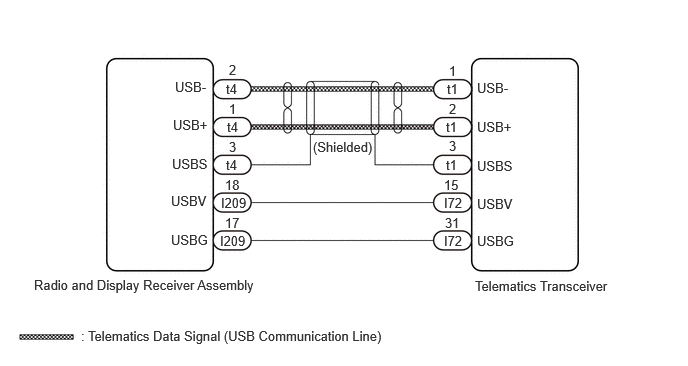
WIRING DIAGRAM
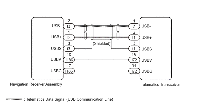
for 10.25 Inch Display with Navigation System or 9 Inch Display without RST Switch
E418547E20
0.354,2.885 2.292,3.135 1.938,0.25 10 false Navigation Receiver Assembly 1.823,0.823 2.302,1.031 0.479,0.208 10 false USB- 1.792,1.625 2.271,1.833 0.479,0.208 10 false USBS 1.802,1.219 2.281,1.427 0.479,0.208 10 false USB+ 2.385,1.052 2.573,1.26 0.188,0.208 10 false 1 2.385,0.646 2.573,0.854 0.188,0.208 10 false 2 2.385,1.448 2.573,1.656 0.188,0.208 10 false 3 4.625,1.844 4.885,2.052 0.26,0.208 10 false 15 2.344,2.24 2.604,2.448 0.26,0.208 10 false 17 0.844,3.417 4.177,3.635 3.333,0.219 10 false : Telematics Data Signal (USB Communication Line) 4.948,2.896 6.521,3.104 1.573,0.208 10 false Telematics Transceiver 1.781,2.01 2.26,2.208 0.479,0.198 10 false USBV 1.781,2.417 2.26,2.615 0.479,0.198 10 false USBG 4.969,2.042 5.448,2.24 0.479,0.198 10 false USBV 4.969,2.427 5.448,2.625 0.479,0.198 10 false USBG 4.656,0.844 5.031,1.083 0.375,0.24 10 false t1 4.635,2.24 4.896,2.448 0.26,0.208 10 false 31 2.344,1.844 2.604,2.052 0.26,0.208 10 false 18 4.677,0.656 4.865,0.865 0.188,0.208 10 false 1 4.677,1.052 4.865,1.26 0.188,0.208 10 false 2 4.677,1.438 4.865,1.646 0.188,0.208 10 false 3 4.969,0.833 5.448,1.042 0.479,0.208 10 false USB- 4.969,1.24 5.448,1.448 0.479,0.208 10 false USB+ 4.969,1.646 5.448,1.854 0.479,0.208 10 false USBS 4.646,1.24 5.021,1.479 0.375,0.24 10 false t1 4.646,1.635 5.021,1.875 0.375,0.24 10 false t1 2.354,0.844 2.729,1.083 0.375,0.24 10 false t3 2.365,1.24 2.74,1.479 0.375,0.24 10 false t3 2.354,1.635 2.729,1.875 0.375,0.24 10 false t3 2.302,2.031 2.677,2.271 0.375,0.24 10 false I186 2.292,2.427 2.667,2.667 0.375,0.24 10 false I186 4.625,2.031 5,2.271 0.375,0.24 10 false I72 4.625,2.427 5,2.667 0.375,0.24 10 false I72 3.26,1.448 3.927,1.688 0.667,0.24 10 false (Shielded)

for 9 Inch Display with RST Switch
E418547
0.354,2.885 2.292,3.135 1.938,0.25 10 false Navigation Receiver Assembly 1.823,0.823 2.302,1.031 0.479,0.208 10 false USB- 1.792,1.625 2.271,1.833 0.479,0.208 10 false USBS 1.802,1.219 2.281,1.427 0.479,0.208 10 false USB+ 2.385,1.052 2.573,1.26 0.188,0.208 10 false 1 2.385,0.646 2.573,0.854 0.188,0.208 10 false 2 2.385,1.448 2.573,1.656 0.188,0.208 10 false 3 4.625,1.844 4.885,2.052 0.26,0.208 10 false 15 2.344,2.24 2.604,2.448 0.26,0.208 10 false 13 0.844,3.417 4.177,3.635 3.333,0.219 10 false : Telematics Data Signal (USB Communication Line) 4.948,2.896 6.521,3.104 1.573,0.208 10 false Telematics Transceiver 1.781,2.01 2.26,2.208 0.479,0.198 10 false USBV 1.781,2.417 2.26,2.615 0.479,0.198 10 false USBG 4.969,2.042 5.448,2.24 0.479,0.198 10 false USBV 4.969,2.427 5.448,2.625 0.479,0.198 10 false USBG 4.656,0.844 5.031,1.083 0.375,0.24 10 false t1 4.635,2.24 4.896,2.448 0.26,0.208 10 false 31 2.375,1.844 2.635,2.052 0.26,0.208 10 false 1 4.677,0.656 4.865,0.865 0.188,0.208 10 false 1 4.677,1.052 4.865,1.26 0.188,0.208 10 false 2 4.677,1.438 4.865,1.646 0.188,0.208 10 false 3 4.969,0.833 5.448,1.042 0.479,0.208 10 false USB- 4.969,1.24 5.448,1.448 0.479,0.208 10 false USB+ 4.969,1.646 5.448,1.854 0.479,0.208 10 false USBS 4.646,1.24 5.021,1.479 0.375,0.24 10 false t1 4.646,1.635 5.021,1.875 0.375,0.24 10 false t1 2.354,0.844 2.729,1.083 0.375,0.24 10 false t2 2.365,1.24 2.74,1.479 0.375,0.24 10 false t2 2.354,1.635 2.729,1.875 0.375,0.24 10 false t2 2.302,2.031 2.677,2.271 0.375,0.24 10 false I170 2.292,2.427 2.667,2.667 0.375,0.24 10 false I170 4.625,2.031 5,2.271 0.375,0.24 10 false I72 4.625,2.427 5,2.667 0.375,0.24 10 false I72 3.271,1.448 3.938,1.688 0.667,0.24 10 false (Shielded)

for 10.25 Inch Display without Navigation System
E418547E34
0.354,2.885 3.01,3.167 2.656,0.281 10 false Radio and Display Receiver Assembly 1.823,0.823 2.302,1.031 0.479,0.208 10 false USB- 1.792,1.625 2.271,1.833 0.479,0.208 10 false USBS 1.802,1.219 2.281,1.427 0.479,0.208 10 false USB+ 2.385,1.052 2.573,1.26 0.188,0.208 10 false 1 2.385,0.646 2.573,0.854 0.188,0.208 10 false 2 2.385,1.448 2.573,1.656 0.188,0.208 10 false 3 4.625,1.844 4.885,2.052 0.26,0.208 10 false 15 2.344,2.24 2.604,2.448 0.26,0.208 10 false 17 0.844,3.417 4.177,3.635 3.333,0.219 10 false : Telematics Data Signal (USB Communication Line) 4.948,2.896 6.521,3.104 1.573,0.208 10 false Telematics Transceiver 1.781,2.01 2.26,2.208 0.479,0.198 10 false USBV 1.781,2.417 2.26,2.615 0.479,0.198 10 false USBG 4.969,2.042 5.448,2.24 0.479,0.198 10 false USBV 4.969,2.427 5.448,2.625 0.479,0.198 10 false USBG 4.656,0.844 5.031,1.083 0.375,0.24 10 false t1 4.635,2.24 4.896,2.448 0.26,0.208 10 false 31 2.344,1.844 2.604,2.052 0.26,0.208 10 false 18 4.677,0.656 4.865,0.865 0.188,0.208 10 false 1 4.677,1.052 4.865,1.26 0.188,0.208 10 false 2 4.677,1.438 4.865,1.646 0.188,0.208 10 false 3 4.969,0.833 5.448,1.042 0.479,0.208 10 false USB- 4.969,1.24 5.448,1.448 0.479,0.208 10 false USB+ 4.969,1.646 5.448,1.854 0.479,0.208 10 false USBS 4.646,1.24 5.021,1.479 0.375,0.24 10 false t1 4.646,1.635 5.021,1.875 0.375,0.24 10 false t1 2.354,0.844 2.729,1.083 0.375,0.24 10 false t4 2.365,1.24 2.74,1.479 0.375,0.24 10 false t4 2.354,1.635 2.729,1.875 0.375,0.24 10 false t4 2.302,2.031 2.677,2.271 0.375,0.24 10 false I209 2.292,2.427 2.667,2.667 0.375,0.24 10 false I209 4.625,2.031 5,2.271 0.375,0.24 10 false I72 4.625,2.427 5,2.667 0.375,0.24 10 false I72 3.26,1.448 3.927,1.688 0.667,0.24 10 false (Shielded)

CAUTION / NOTICE / HINT

NOTICE:
·

Depending on the parts that are replaced during vehicle inspection or maintenance, performing initialization, registration or calibration may be needed. Refer to Precaution for Telematics System.

Click hereAudio / Visual / Telematics>TELEMATICS>TELEMATICS SYSTEM (for Gasoline Model)>PRECAUTION

·

Before replacing the telematics transceiver, refer to Service Bulletin.


PROCEDURE

1.CHECK DTC OUTPUT
a.

Clear the DTCs.

Body Electrical > Telematics > Clear DTCs
50002 459

b.

Recheck for DTCs and check if the same DTC is output again.

Body Electrical > Telematics > Trouble Codes
50001 459

Result:
Result Proceed to
No DTCs are output. A
DTCs are output. B


A

B

2.CHECK MODEL
2.CHECK MODEL
a.

Choose the model to be inspected.

Result:
Result Proceed to
w/ Navigation System A
w/o Navigation System B


A

3.CHECK HARNESS AND CONNECTOR (TELEMATICS TRANSCEIVER - NAVIGATION RECEIVER ASSEMBLY)

B

7.CHECK HARNESS AND CONNECTOR (TELEMATICS TRANSCEIVER - RADIO AND DISPLAY RECEIVER ASSEMBLY)
3.CHECK HARNESS AND CONNECTOR (TELEMATICS TRANSCEIVER - NAVIGATION RECEIVER ASSEMBLY)
a.

for 10.25 Inch Display with Navigation System or 9 Inch Display without RST Switch:

i.

Disconnect the I186 navigation receiver assembly connector.


b.

for 9 Inch Display with RST Switch:

i.

Disconnect the I170 navigation receiver assembly connector.


c.

Disconnect the I72 telematics transceiver connector.


d.

Measure the resistance according to the value(s) in the table below.

Standard Resistance:
for 10.25 Inch Display with Navigation System or 9 Inch Display without RST Switch
Tester Connection Condition Specified Condition
I186-18 (USBV) - I72-15 (USBV) Always Below 1 Ω
I186-17 (USBG) - I72-31 (USBG) Always Below 1 Ω
I186-18 (USBV) or I72-15 (USBV) - Body ground Always 10 kΩ or higher
I186-17 (USBG) or I72-31 (USBG) - Body ground Always 10 kΩ or higher

for 9 Inch Display with RST Switch
Tester Connection Condition Specified Condition
I170-1 (USBV) - I72-15 (USBV) Always Below 1 Ω
I170-13 (USBG) - I72-31 (USBG) Always Below 1 Ω
I170-1 (USBV) or I72-15 (USBV) - Body ground Always 10 kΩ or higher
I170-13 (USBG) or I72-31 (USBG) - Body ground Always 10 kΩ or higher


Result:
Proceed to
OK
NG


OK

4.CHECK HARNESS AND CONNECTOR (TELEMATICS TRANSCEIVER - NAVIGATION RECEIVER ASSEMBLY)

NG

REPAIR OR REPLACE HARNESS OR CONNECTOR

4.CHECK HARNESS AND CONNECTOR (TELEMATICS TRANSCEIVER - NAVIGATION RECEIVER ASSEMBLY)
a.

Check the installation condition.

i.

Check the USB communication lines (digital communication line) between the navigation receiver assembly and the telematics transceiver for any installation or connection problems.


b.

for 10.25 Inch Display with Navigation System or 9 Inch Display without RST Switch:

i.

Disconnect the t3 navigation receiver assembly connector.


c.

for 9 Inch Display with RST Switch:

i.

Disconnect the t2 navigation receiver assembly connector.


d.

Disconnect the t1 telematics transceiver connector.


e.

Measure the resistance according to the value(s) in the table below.

Standard Resistance:
for 10.25 Inch Display with Navigation System or 9 Inch Display without RST Switch
Tester Connection Condition Specified Condition
t3-1 (USB+) - t1-2 (USB+) Always Below 1 Ω
t3-2 (USB-) - t1-1 (USB-) Always Below 1 Ω
t3-3 (USBS) - t1-3 (USBS) Always Below 1 Ω
t3-1 (USB+) or t1-2 (USB+) - Body ground Always 10 kΩ or higher
t3-2 (USB-) or t1-1 (USB-) - Body ground Always 10 kΩ or higher
t3-3 (USBS) or t1-3 (USBS) - Body ground Always 10 kΩ or higher

for 9 Inch Display with RST Switch
Tester Connection Condition Specified Condition
t2-1 (USB+) - t1-2 (USB+) Always Below 1 Ω
t2-2 (USB-) - t1-1 (USB-) Always Below 1 Ω
t2-3 (USBS) - t1-3 (USBS) Always Below 1 Ω
t2-1 (USB+) or t1-2 (USB+) - Body ground Always 10 kΩ or higher
t2-2 (USB-) or t1-1 (USB-) - Body ground Always 10 kΩ or higher
t2-3 (USBS) or t1-3 (USBS) - Body ground Always 10 kΩ or higher


Result:
Proceed to
OK
NG


OK

5.REPLACE TELEMATICS TRANSCEIVER

NG

REPAIR OR REPLACE HARNESS OR CONNECTOR

5.REPLACE TELEMATICS TRANSCEIVER

Result:
Proceed to
NEXT


NEXT

6.CHECK DTC OUTPUT
6.CHECK DTC OUTPUT
a.

Clear the DTCs.

Body Electrical > Telematics > Clear DTCs
50002 459

b.

Recheck for DTCs and check if the same DTC is output again.

Body Electrical > Telematics > Trouble Codes
50001 459

Result:
Result Proceed to
No DTCs are output. A
DTCs are output. B


A

END

B

7.CHECK HARNESS AND CONNECTOR (TELEMATICS TRANSCEIVER - RADIO AND DISPLAY RECEIVER ASSEMBLY)
a.

Disconnect the I209 radio and display receiver assembly connector.


b.

Disconnect the I72 telematics transceiver connector.


c.

Measure the resistance according to the value(s) in the table below.

Standard Resistance:
Tester Connection Condition Specified Condition
I209-18 (USBV) - I72-15 (USBV) Always Below 1 Ω
I209-17 (USBG) - I72-31 (USBG) Always Below 1 Ω
I209-18 (USBV) or I72-15 (USBV) - Body ground Always 10 kΩ or higher
I209-17 (USBG) or I72-31 (USBG) - Body ground Always 10 kΩ or higher


Result:
Proceed to
OK
NG


OK

8.CHECK HARNESS AND CONNECTOR (TELEMATICS TRANSCEIVER - RADIO AND DISPLAY RECEIVER ASSEMBLY)

NG

REPAIR OR REPLACE HARNESS OR CONNECTOR

8.CHECK HARNESS AND CONNECTOR (TELEMATICS TRANSCEIVER - RADIO AND DISPLAY RECEIVER ASSEMBLY)
a.

Check the installation condition.

i.

Check the USB communication lines (digital communication line) between the radio and display receiver assembly and the telematics transceiver for any installation or connection problems.


b.

Disconnect the t4 radio and display receiver assembly connector.


c.

Disconnect the t1 telematics transceiver connector.


d.

Measure the resistance according to the value(s) in the table below.

Standard Resistance:
Tester Connection Condition Specified Condition
t4-1 (USB+) - t1-2 (USB+) Always Below 1 Ω
t4-2 (USB-) - t1-1 (USB-) Always Below 1 Ω
t4-3 (USBS) - t1-3 (USBS) Always Below 1 Ω
t4-1 (USB+) or t1-2 (USB+) - Body ground Always 10 kΩ or higher
t4-2 (USB-) or t1-1 (USB-) - Body ground Always 10 kΩ or higher
t4-3 (USBS) or t1-3 (USBS) - Body ground Always 10 kΩ or higher


Result:
Proceed to
OK
NG


OK

9.REPLACE TELEMATICS TRANSCEIVER

NG

REPAIR OR REPLACE HARNESS OR CONNECTOR

9.REPLACE TELEMATICS TRANSCEIVER

Result:
Proceed to
NEXT


NEXT

10.CHECK DTC OUTPUT
10.CHECK DTC OUTPUT
a.

Clear the DTCs.

Body Electrical > Telematics > Clear DTCs
50002 459

b.

Recheck for DTCs and check if the same DTC is output again.

Body Electrical > Telematics > Trouble Codes
50001 459

Result:
Result Proceed to
No DTCs are output. A
DTCs are output. B


A

END

B