NR Series BATTERY / CHARGING CHARGING SYSTEM P161A87 Lost Communication with Alternator Missing Message
DESCRIPTION
The ECM communicates with the generator assembly via LIN communication. If a LIN communication error is detected, the ECM stores this DTC.
| DTC No. | Detection Item | DTC Detection Condition | Trouble Area | Warning Indicate | Memory | Note |
|---|---|---|---|---|---|---|
| P161A87 | Lost Communication with Alternator Missing Message | Generator assembly or ECM communication stops for approximately 17 minutes or more with the ignition switch ON.
(1 trip detection logic) |
·
Wire harness or connector ·
Generator assembly ·
ECM |
Charge warning is not displayed | DTC stored | SAE Code: P161A |
WIRING DIAGRAM
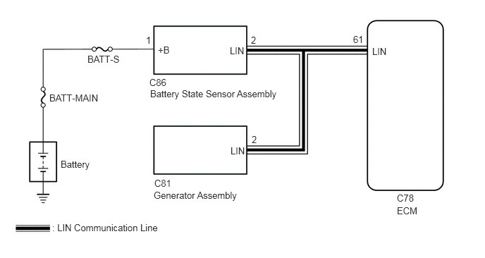
CAUTION / NOTICE / HINT
- NOTICE:
-
Make sure to perform the necessary procedures (adjustment, calibration, initialization, or registration) after parts related to the charging system have been removed/installed or replaced.
PROCEDURE
Check the charging system.
- Result:
Proceed to OK NG
OK
NG
Disconnect the C78 ECM connector.
Disconnect the C81 generator assembly connector.
Disconnect the C86 battery state sensor assembly connector.
Measure the resistance according to the value(s) in the table below.
- Standard Resistance:
Tester Connection Condition Specified Condition C78-61 (LIN) - C81-2 (LIN) or C86-2 (LIN) Always Below 1 Ω C78-61 (LIN), C81-2 (LIN) or C86-2 (LIN) - Body ground Always 10 kΩ or higher
- Result:
Proceed to OK NG
OK
NG
Connect the GTS to the DLC3.
Turn the ignition switch to ON.
Turn the GTS on.
Enter the following menus: Powertrain / Engine / Trouble Codes.
Check for DTCs, and then write them down.
- Powertrain > Engine > Trouble Codes
- 50001 372
Enter the following menus: Powertrain / Engine / Trouble Codes.
Clear the DTCs.
- Powertrain > Engine > Clear DTCs
- 50002 372
Turn the ignition switch off and wait for at least 30 seconds.
- Result:
Proceed to NEXT
NEXT
Connect the GTS to the DLC3.
Start the engine.
Allow the engine to idle for approximately 17 minutes or more.
Turn the GTS on.
Enter the following menus: Powertrain / Engine / Trouble Codes.
Check for DTCs.
- Powertrain > Engine > Trouble Codes
- 50001 372
- Result:
Result Proceed to Only DTC P161A87 is output A DTC P161A87 and P162B87 are output B DTCs are not output C
A
B
C