NR Series ENGINE MECHANICAL ENGINE ON-VEHICLE INSPECTION
CAUTION / NOTICE / HINT
- CAUTION:
- ·
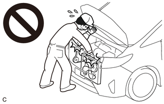
When working near the engine room while the engine has started or the ignition switch is ON, do not touch the V-ribbed belt or rotating components such as the fan, etc.
·Touching the V-ribbed belt or rotating components such as the fan, etc. could result in your hand or clothing getting caught and pulled in.
PROCEDURE

 1.INSPECT ENGINE COOLANT
2.INSPECT ENGINE OIL
3.INSPECT BATTERY CONDITION
19100P
4.INSPECT SPARK PLUG
17801
5.INSPECT AIR CLEANER FILTER ELEMENT SUB-ASSEMBLY
16361A
6.INSPECT V-RIBBED BELT
16620
7.INSPECT V-RIBBED BELT TENSIONER ASSEMBLY
Remove the V-ribbed belt.
Turn the V-ribbed belt tensioner assembly clockwise and counterclockwise and check that it turns smoothly and does not catch.
- HINT:
-
If the V-ribbed belt tensioner assembly does not turn smoothly or catches, replace the V-ribbed belt tensioner assembly.
Install the V-ribbed belt.
13750
8.INSPECT VALVE LASH ADJUSTER ASSEMBLY NOISE
Rev up the engine several times. Check that the engine does not emit unusual noises.
If unusual noises occur, warm up the engine and idle it for 30 minutes or more, then perform the inspection.
- HINT:
-
If any defects or problems are found during the inspection, perform valve lash adjuster assembly inspection.
9.INSPECT IGNITION TIMING
Warm up and stop the engine.
Connect the GTS to the DLC3.
Start the engine and run it at idle.
Turn the GTS on.
Enter the following menus: Powertrain / Engine / Data List / Ignition Timing Cylinder #1.
- Powertrain > Engine > Data List
-
Tester Display Ignition Timing Cylinder #1 - 50003 372 213
- Standard Ignition Timing:
-5 to 25° BTDC at idle
- NOTICE:
- ·
Check the ignition timing with the cooling fans off.
·Turn off all electrical systems and the A/C.
·When checking the ignition timing, the transaxle should be in neutral or park.
Enter the following menus: Powertrain / Engine / Active Test / Activate the TC Terminal / ON.
- Powertrain > Engine > Active Test
-
Active Test Display Activate the TC Terminal -
Data List Display Ignition Timing Cylinder #1 - 50004 372 22 213
Monitor Ignition Timing Cylinder #1 of the Data List.
- Standard Ignition Timing:
8 to 12° BTDC at idle
Enter the following menus: Powertrain / Engine / Active Test / Activate the TC Terminal / OFF.
Check that the ignition timing advances immediately when the engine speed is increased.
10.INSPECT ENGINE IDLE SPEED
Warm up and stop the engine.
Connect the GTS to the DLC3.
Start the engine and run it at idle.
Turn the GTS on.
Enter the following menus: Powertrain / Engine / Data List / Engine Speed.
- Powertrain > Engine > Data List
-
Tester Display Engine Speed - 50003 372 211
Read the value displayed on the tester.
- Standard Idle Speed:
680 to 780 rpm
- NOTICE:
- ·
Check the engine idle speed with the cooling fans off.
·Turn off all electrical systems and the A/C.
·When checking the engine idle speed, the transaxle should be in neutral or park.
11.INSPECT COMPRESSION
- NOTICE:
-
Keep the spark plug holes free of foreign matter when measuring the compression pressure.
Warm up and stop the engine.
Remove the 4 spark plugs.
Click hereGeneral>MAINTENANCE>NR Series SPARK PLUG>REMOVAL201906,999999,_V1,_080956,_0392145,RM100000001HO9H,
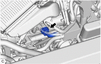
Disconnect the engine wire connector as shown in the illustration.
- NOTICE:
-
Disable fuel injection in order to prevent catalyst damage due to unburned gasoline.
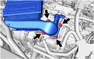
Remove the 2 bolts and 2 nuts and disconnect the intercooler assembly from the throttle body with motor assembly.
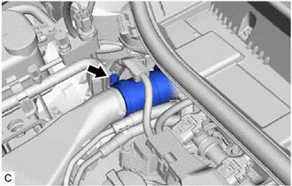
Loosen the hose clamp and remove the intercooler assembly from the air tube assembly and throttle body with motor assembly.
Disconnect the throttle body with motor assembly.
Check the cylinder compression pressure.
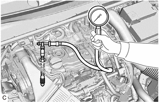
Insert a compression gauge into the spark plug hole.
While cranking the engine, measure the compression pressure.
- Standard Compression Pressure:
1080 kPa (11.0 kgf/cm2, 157 psi)
- Minimum Compression Pressure:
880 kPa (9.0 kgf/cm2, 128 psi)
- Pressure Difference between Each Cylinder:
100 kPa (1.0 kgf/cm2, 15 psi) or less
- NOTICE:
- ·
Always use a fully charged battery to obtain an engine speed of 250 rpm or more.
·Inspect all cylinders in the same way.
·Measure the compression pressure as quickly as possible.
If the cylinder compression pressure is low, pour a small amount of engine oil into the cylinder through the spark plug hole and inspect it again.
- HINT:
- ·
If adding oil increases the compression pressure, the piston rings and/or cylinder bore may be worn or damaged.
·If the compression pressure stays low, a valve may be stuck or seated improperly, or there may be leaks in the cylinder head gasket.
Connect the throttle body with motor assembly.
Temporarily install the intercooler assembly to the air tube assembly and throttle body with motor assembly with the hose clamp.
Temporarily install the intercooler assembly to the throttle body with motor assembly with the 2 bolts and 2 nuts.
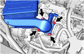
Tighten the 2 bolts and 2 nuts in the order shown in the illustration.
- Torque:
- 10 N*m (102 kgf*cm, 7 ft.*lbf)
Tighten the hose clamp.
- Torque:
- 6.3 N*m (64 kgf*cm, 56 in.*lbf)
Connect the engine wire connector.
Install the 4 spark plugs.
Clear the DTCs.
- NOTICE:
-
After the inspection, clear the DTCs, check for DTCs again and make sure the normal system code is output.
12.INSPECT CO/HC
- HINT:
-
This check determines whether or not the idle CO/HC complies with regulations.
Start the engine.
Run the engine at 2500 rpm for approximately 180 seconds.
Insert a CO/HC meter testing probe at least 40 cm (1.31 ft.) into the tailpipe during idle.
Immediately check the CO/HC concentration during idle and when the engine is running at 2500 rpm.
- HINT:
-
When performing a 2 mode (with the engine idling/running at 2500 rpm) test, the measurement procedures are determined by applicable local regulations.
-
If the CO/HC concentration does not comply with the regulations, perform troubleshooting in the order given below.
See the following table for possible causes, then inspect the applicable parts and repair them if necessary.
| CO | HC | Problem | Cause |
|---|---|---|---|
| Normal | High | Rough idle | 1.
Faulty ignition: -
Incorrect valve timing -
Fouled, shorted or improperly gapped spark plugs 2.
Incorrect valve clearance (valve lash adjuster assembly) 3.
Leaks in intake or exhaust valves 4.
Leaks in cylinders |
| Low | High | Rough idle (Fluctuating HC reading) | 1.
Vacuum leaks: -
PCV hoses -
Intake manifold -
Throttle with motor body assembly 2.
Lean mixture causing misfire |
| High | High | Rough idle (Black smoke from exhaust) | 1.
Restricted air cleaner filter element sub-assembly 2.
Plugged PCV valve 3.
Faulty SFI systems: -
Fuel pressure regulator assembly -
Engine coolant temperature sensor -
Mass air flow meter sub-assembly -
ECM -
Fuel injector assemblies -
Throttle position sensor (built into throttle with motor body assembly) |