8ZR-FXE ENGINE CONTROL SFI SYSTEM P045011 Evaporative Emission System Pressure Sensor/Switch Circuit Short to Ground P045015 Evaporative Emission System Pressure Sensor/Switch Circuit Short to Battery or Open P04502F Evaporative Emission System Pressure Sensor/Switch Signal Erratic
DTC SUMMARY
| DTC No. | Detection Item | DTC Detection Condition | Trouble Area | MIL | Memory | Note |
|---|---|---|---|---|---|---|
| P045011 | Evaporative Emission System Pressure Sensor/Switch Circuit Short to Ground | EVAP pressure sensor voltage is less than 0.45 V for 0.5 seconds or more. | ·
Canister pump module ·
Connector/wire harness (Canister pump module - ECM) ·
ECM |
Comes on | DTC stored | SAE Code: P0452 |
| P045015 | Evaporative Emission System Pressure Sensor/Switch Circuit Short to Battery or Open | EVAP pressure sensor voltage is higher than 4.9 V for 0.5 seconds or more. | ·
Canister pump module ·
Connector/wire harness (Canister pump module - ECM) ·
ECM |
Comes on | DTC stored | SAE Code: P0453 |
| P04502F | Evaporative Emission System Pressure Sensor/Switch Signal Erratic | Canister pressure sensor output voltage fluctuates frequently for a certain amount of time. | ·
Canister pump module ·
Connector/wire harness (Canister pump module - ECM) ·
EVAP system hose (pipe from air inlet port to canister pump module, canister filter, fuel tank vent hose) ·
ECM |
Comes on | DTC stored | SAE Code: P0451 |
| DTC No. | Monitoring Item | Detection Timing | Detection Logic | SAE Code |
|---|---|---|---|---|
| P045011 | Canister pressure sensor low input | ·
Power switch on (IG) ·
EVAP monitoring (power switch off) |
1 trip | P0452 |
| P045015 | Canister pressure sensor high input | ·
Power switch on (IG) ·
EVAP monitoring (power switch off) |
1 trip | P0453 |
| P04502F | Canister pressure sensor abnormal voltage fluctuation (Noise monitor) | ·
EVAP monitoring (power switch off) ·
Engine running |
2 trip | P0451 |
- HINT:
-
The canister pressure sensor is built into the canister pump module.
DESCRIPTION
Refer to EVAP (Evaporative Emission) System.
MONITOR DESCRIPTION
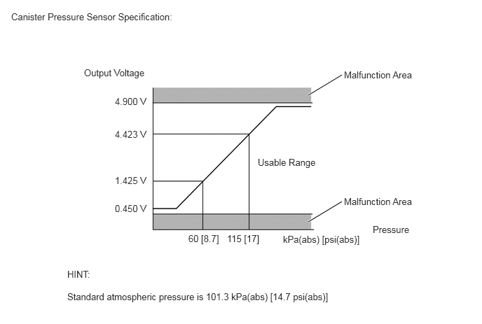
DTC P045011: Canister pressure sensor voltage low
If the canister pressure sensor output voltage (pressure) is less than 0.45 V: 42.110 kPa(abs) [6.106 psi(abs)], the ECM interprets this as an open or short circuit in the canister pressure sensor or its circuit, and stops the EVAP system monitor. If any deterioration has occurred, the ECM will illuminate the MIL and store this DTC (1 trip detection logic).
DTC P045015: Canister pressure sensor voltage high
If the canister pressure sensor output voltage (pressure) is higher than 4.9 V: 123.761 kPa(abs) [17.945 psi(abs)], the ECM interprets this as an open or short circuit in the canister pressure sensor or its circuit, and stops the EVAP system monitor. If any deterioration has occurred, the ECM will illuminate the MIL and store this DTC (1 trip detection logic).
DTC P04502F: Canister pressure sensor abnormal voltage fluctuation (Noise monitor)
If the canister pressure sensor output voltage fluctuates rapidly for 10 seconds, the ECM stops the EVAP system monitor. The ECM interprets this as the canister pressure sensor voltage fluctuating, and stops the EVAP system monitor. The ECM then illuminates the MIL and stores this DTC (2 trip detection logic).
MONITOR STRATEGY
| Required Sensors/Components | Canister pump module |
| Frequency of Operation | Continuous |
CONFIRMATION DRIVING PATTERN
- NOTICE:
- ·
The Evaporative System Check (Automatic Mode) consists of 9 steps performed automatically by the GTS. It takes a maximum of approximately 40 minutes.
·Do not perform the Evaporative System Check when the fuel tank is more than 90% full because the cut-off valve may be closed, making the fuel tank leak check unavailable.
·Do not start the engine during this operation.
·When the temperature of the fuel is 35°C (95°F) or higher, a large amount of vapor will from and any check result will be inaccurate. When performing the Evaporative System Check, keep the fuel temperature less than 35°C (95°F).
- HINT:
- ·
After repair has been completed, clear the DTC and then check that the vehicle has returned to normal by performing the following All Readiness check procedure.
·When clearing the permanent DTCs, refer to the "CLEAR PERMANENT DTC" procedure.
Connect the GTS to the DLC3.
Turn the power switch on (IG).
Turn the GTS on.
Clear the DTCs (even if no DTCs are stored, perform the clear DTC procedure).
Turn the power switch off and wait for at least 30 seconds.
Turn the engine switch on (IG) [A].
Turn the GTS on.
Enter the following menus: Powertrain / Engine / Data List / Intake Air Temperature.
Check that the intake air temperature is between 4.4 and 50°C (39.9 and 122°F) [B].
Enter the following menus: Powertrain / Engine / Utility / Evaporative System Check / Automatic Mode [C].
After the Evaporative System Check is completed, check for All Readiness by entering the following menus: Powertrain / Engine / Utility / All Readiness.
Input the DTC: P045011, P045015 or P04502F.
Check the DTC judgment result.
| GTS Display | Description |
|---|---|
| NORMAL | ·
DTC judgment completed ·
System normal |
| ABNORMAL | ·
DTC judgment completed ·
System abnormal |
| INCOMPLETE | ·
DTC judgment not completed ·
Perform driving pattern after confirming DTC enabling conditions |
- HINT:
- ·
If the judgment result is NORMAL, the system is normal.
·If the judgment result is ABNORMAL, the system is malfunctioning.
·[A] to [C]: Normal judgment procedure.
The normal judgment procedure is used to complete DTC judgment and also used when clearing permanent DTCs.
·When clearing the permanent DTCs, do not disconnect the cable from the auxiliary battery terminal or attempt to clear the DTCs during this procedure, as doing so will clear the universal trip and normal judgment histories.
WIRING DIAGRAM
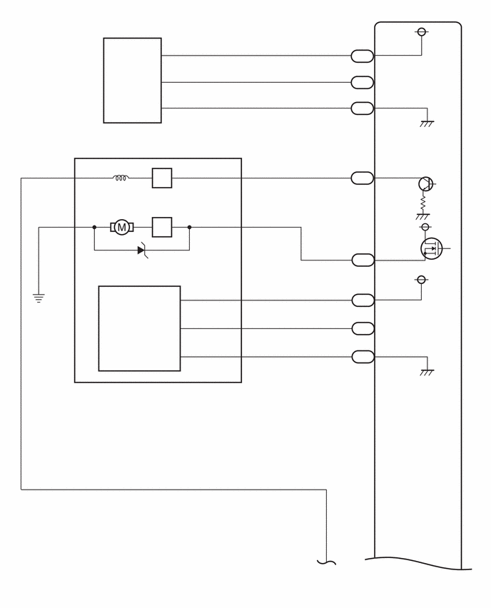
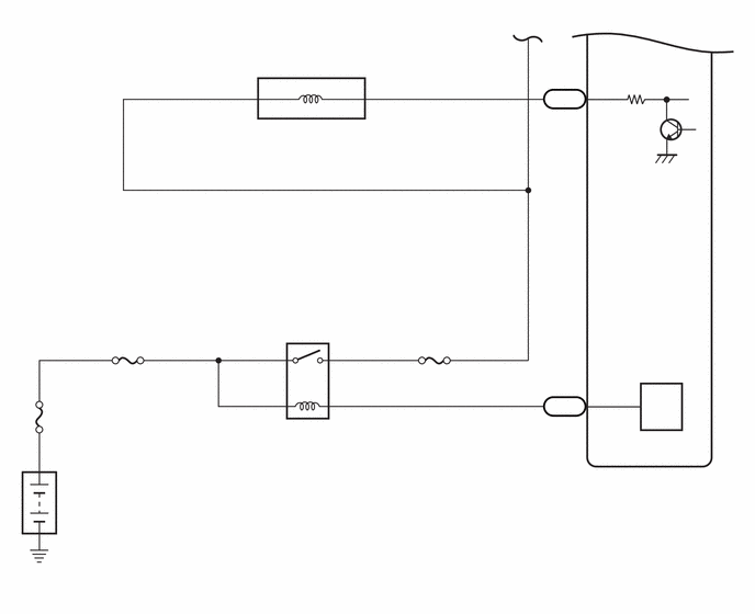
CAUTION / NOTICE / HINT
- NOTICE:
- ·
Vehicle Control History may be stored in the hybrid vehicle control ECU assembly if the engine is malfunctioning. Certain vehicle condition information is recorded when Vehicle Control History is stored. Reading the vehicle conditions recorded in both the Freeze Frame Data and Vehicle Control History can be useful for troubleshooting.
(Select Powertrain in Health Check and then check the time stamp data.)
·If any "Engine Malfunction" Vehicle Control History item has been stored in the hybrid vehicle control ECU assembly, make sure to clear it. However, as all Vehicle Control History items are cleared simultaneously, if any Vehicle Control History items other than "Engine Malfunction" are stored, make sure to perform any troubleshooting for them before clearing Vehicle Control History.
·When a vehicle which has any of these DTCs stored is brought into the workshop, do not change the condition of the vehicle. For example, do not tighten the fuel tank cap assembly.
·The GTS is required to conduct the following diagnostic troubleshooting procedure.
·Inspect the fuses for circuits related to this system before performing the following procedure.
PROCEDURE
Connect the GTS to the DLC3.
Turn the power switch on (IG) (do not start the engine).
Turn the GTS on.
Enter the following menus: Powertrain / Engine / Trouble Codes.
Read the DTCs.
- Powertrain > Engine > Trouble Codes
- 50001 372
Enter the following menus: Powertrain / Engine / Data List / Vapor Pressure Pump.
- Powertrain > Engine > Data List
-
Tester Display Vapor Pressure Pump - 50003 372 160
Read the EVAP (Evaporative Emission) pressure displayed on the GTS.
- Result:
Display (DTC Output) Test Result Suspected Trouble Area Proceed to P045011 Less than 42.11009 kPa(abs) [6.10596 psi(abs)] ·Wire harness/connector (canister pressure sensor - ECM)
·Canister pressure sensor
·Short in ECM circuit
A P045015 Higher than 123.76147 kPa(abs) [17.94541 psi(abs)] ·Wire harness/connector (canister pressure sensor - ECM)
·Canister pressure sensor
·Open in ECM circuit
B P04502F - Canister pressure sensor C
A
B
C
Disconnect the ECM connector.
Measure the resistance according to the value(s) in the table below.
- Result:
Tester Connection Condition Specified Condition Suspected Trouble Area Proceed to A46-40 (PPMP) - Body ground Always Below 10 Ω ·Wire harness/connector (canister pressure sensor - ECM)
·Short in canister pressure sensor circuit
A 10 kΩ or higher ·Wire harness/connector (canister pressure sensor - ECM)
·Short in ECM circuit
B
A
B
Disconnect the canister pump module connector.
Disconnect the ECM connector.
Measure the resistance according to the value(s) in the table below.
- Result:
Tester Connection Condition Specified Condition Suspected Trouble Area Proceed to A46-40 (PPMP) - Body ground Always 10 kΩ or higher Short in canister pressure sensor circuit A Below 10 Ω Short in wire harness/connector (canister pressure sensor - ECM) B
A
B
- Result:
Proceed to NEXT
NEXT
Disconnect the canister pump module connector.
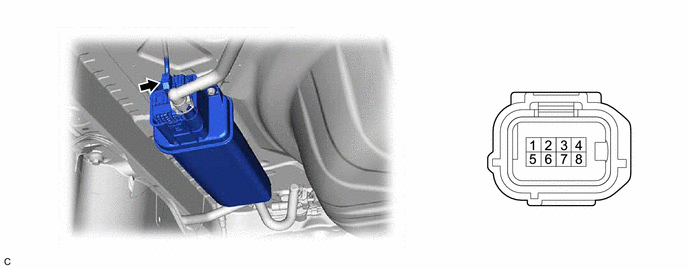
| *a | Front view of wire harness connector
(to Canister Pump Module) |
- | - |
Measure the resistance according to the value(s) in the table below.
- Standard Resistance:
Tester Connection Condition Specified Condition O133-8 (SGND) - Body ground Always 100 Ω or less
Turn the power switch on (IG).
Measure the voltage according to the value(s) in the table below.
- Standard Voltage:
Tester Connection Condition Specified Condition O133-6 (VCC) - Body ground Power switch on (IG) 4.5 to 5.5 V O133-7 (VOUT) - Body ground Power switch on (IG) 4.5 to 5.5 V
- Result:
Test Result Suspected Trouble Area Proceed to Voltage and resistance within standard ranges Open in canister pressure sensor circuit A Voltage and/or resistance outside standard ranges Open in wire harness/connector (canister pressure sensor - ECM) B
A
B
Replace the canister pump module.
- NOTICE:
- ·
When replacing the canister pump module, check the inside of the canister pump module and canister, and related pipes for water, fuel and other liquids. If liquids are present, check for disconnections and/or cracks in the following: 1) the pipe from the air inlet port to the canister pump module; 2) the canister filter; and 3) the fuel tank vent hose. If liquids are present in the inside of the canister, replace the canister and canister pump module.
·Check for filter blockage in the canister. If the charcoal filter inside the canister is clogged, replace the canister and canister pump module.
·Check for filter blockage in the canister filter. If there is blockage in the canister filter, replace the canister filter.
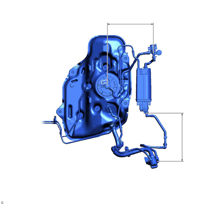
| *1 | Fuel Tank Vent Hose | *2 | Air Inlet Port |
| *3 | Vent Hose | *4 | Fuel Tank |
| *5 | Canister Pump Module
·
Canister Pressure Sensor ·
Leak Detection Pump ·
Vent Valve |
*6 | Canister |
| *7 | Canister Filter | *8 | Fuel Tank Pressure Sensor |
| *9 | Fuel Tank Cap Assembly | *10 | Fuel Vapor-containment Valve |
| *a | Inspection Area
(Check for disconnection and/or cracks) |
- | - |
- Result:
Proceed to NEXT
NEXT
- Result:
Proceed to NEXT
NEXT
Connect the GTS to the DLC3.
Turn the power switch on (IG).
Turn the GTS on.
Clear the DTCs.
- Powertrain > Engine > Clear DTCs
- 50002 372
Turn the power switch off and wait for at least 30 seconds.
- Result:
Proceed to NEXT
NEXT
Perform the Evaporative System Check using the GTS, referring to the Confirmation Driving Pattern.
Enter the following menus: Powertrain / Engine / Utility / All Readiness.
- Powertrain > Engine > Utility
-
Tester Display All Readiness - 50005 372 1020
Input the DTC: P045011, P045015 or P04502F.
Check the DTC judgment result.
- Result:
GTS Display Description NORMAL ·DTC judgment completed
·System normal
ABNORMAL ·DTC judgment completed
·System abnormal
INCOMPLETE ·DTC judgment not completed
·Perform driving pattern after confirming DTC enabling conditions
- Result:
Proceed to NEXT
NEXT