8ZR-FXE ENGINE CONTROL SFI SYSTEM P040314 Exhaust Gas Recirculation "A" Control Circuit 1 Open P140000 Exhaust Gas Recirculation "A" Control Circuit 2 Open P140596 Exhaust Gas Recirculation "A" Control Circuit 3 Open P141004 Exhaust Gas Recirculation "A" Control Circuit 4 Open
DESCRIPTION
Refer to DTC P04019C.
| DTC No. | Detection Item | DTC Detection Condition | Trouble Area | MIL | Memory | Note |
|---|---|---|---|---|---|---|
| P040314 | Exhaust Gas Recirculation "A" Control Circuit 1 Open | Open or short in EGR1 circuit for 1 second or more (1 trip detection logic). | ·
Open or short in EGR valve assembly circuit ·
EGR valve assembly ·
ECM |
Comes on | DTC stored | SAE Code: P0403 |
| P140000 | Exhaust Gas Recirculation "A" Control Circuit 2 Open | Open or short in EGR2 circuit for 1 second or more (1 trip detection logic). | ·
Open or short in EGR valve assembly circuit ·
EGR valve assembly ·
ECM |
Comes on | DTC stored | SAE Code: P0403 |
| P140596 | Exhaust Gas Recirculation "A" Control Circuit 3 Open | Open or short in EGR3 circuit for 1 second or more (1 trip detection logic). | ·
Open or short in EGR valve assembly circuit ·
EGR valve assembly ·
ECM |
Comes on | DTC stored | SAE Code: P0403 |
| P141004 | Exhaust Gas Recirculation "A" Control Circuit 4 Open | Open or short in EGR4 circuit for 1 second or more (1 trip detection logic). | ·
Open or short in EGR valve assembly circuit ·
EGR valve assembly ·
ECM |
Comes on | DTC stored | SAE Code: P0403 |
MONITOR DESCRIPTION
These DTCs are stored if an open or short in the EGR valve assembly circuit is detected.
Example:
If the EGR1, EGR2, EGR3 or EGR4 terminal output voltage is excessively low, but the step motor is still operating, the ECM determines that there is a short in the EGR valve assembly circuit, illuminate the MIL and stores a DTC.
If the EGR1, EGR2, EGR3 or EGR4 terminal output voltage is excessively low, and the step motor is not operating, the ECM determines that there is an open in the EGR valve assembly circuit, illuminate the MIL and stores a DTC.
MONITOR STRATEGY
| Frequency of Operation | Continuous |
CONFIRMATION DRIVING PATTERN
- HINT:
- ·
After repair has been completed, clear the DTC and then check that the vehicle has returned to normal by performing the following All Readiness check procedure.
·When clearing the permanent DTCs, refer to the "CLEAR PERMANENT DTC" procedure.
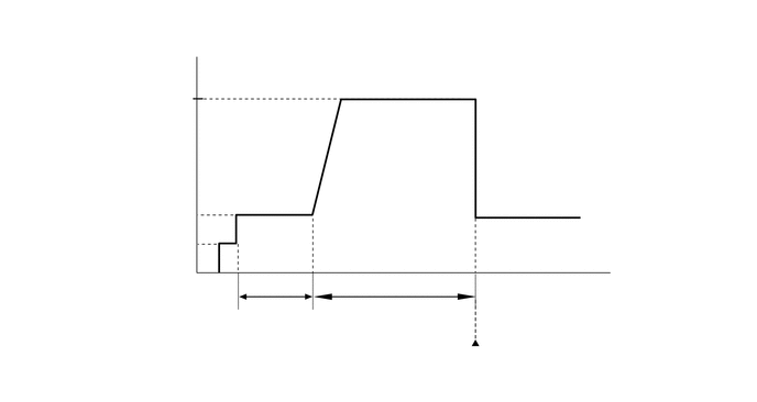
Connect the GTS to the DLC3.
Turn the power switch on (IG).
Turn the GTS on.
Clear the DTCs (even if no DTCs are stored, perform the clear DTC procedure).
Turn the power switch off and wait for at least 30 seconds.
Turn the power switch on (IG) [A].
Turn the GTS on.
Put the engine in Inspection Mode (Maintenance Mode).
Start the engine and warm it up [B].
With the engine running, drive the vehicle at 20 km/h (12 mph) or more for 10 minutes or more [C].
- CAUTION:
-
When performing the confirmation driving pattern, obey all speed limits and traffic laws.
- HINT:
-
If the engine stops, further depress the accelerator pedal to restart the engine.
Enter the following menus: Powertrain / Engine / Trouble Codes [D].
Read the pending DTCs.
- HINT:
- ·
If a pending DTC is output, the system is malfunctioning.
·If a pending DTC is not output, perform the following procedure.
Enter the following menus: Powertrain / Engine / Utility / All Readiness.
Input the DTC: P040314, P140000, P140596 or P141004.
Check the DTC judgment result.
| GTS Display | Description |
|---|---|
| NORMAL | ·
DTC judgment completed ·
System normal |
| ABNORMAL | ·
DTC judgment completed ·
System abnormal |
| INCOMPLETE | ·
DTC judgment not completed ·
Perform driving pattern after confirming DTC enabling conditions |
- HINT:
- ·
If the judgment result is NORMAL, the system is normal.
·If the judgment result is ABNORMAL, the system is malfunctioning.
·[A] to [D]: Normal judgment procedure.
The normal judgment procedure is used to complete DTC judgment and also used when clearing permanent DTCs.
·When clearing the permanent DTCs, do not disconnect the cable from the auxiliary battery terminal or attempt to clear the DTCs during this procedure, as doing so will clear the universal trip and normal judgment histories.
WIRING DIAGRAM
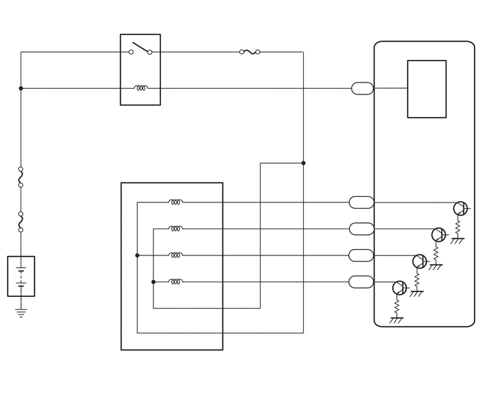
CAUTION / NOTICE / HINT
- NOTICE:
- ·
Vehicle Control History may be stored in the hybrid vehicle control ECU assembly if the engine is malfunctioning. Certain vehicle condition information is recorded when Vehicle Control History is stored. Reading the vehicle conditions recorded in both the Freeze Frame Data and Vehicle Control History can be useful for troubleshooting.
(Select Powertrain in Health Check and then check the time stamp data.)
·If any "Engine Malfunction" Vehicle Control History item has been stored in the hybrid vehicle control ECU assembly, make sure to clear it. However, as all Vehicle Control History items are cleared simultaneously, if any Vehicle Control History items other than "Engine Malfunction" are stored, make sure to perform any troubleshooting for them before clearing Vehicle Control History.
·Inspect the fuses for circuits related to this system before performing the following procedure.
- HINT:
-
Read Freeze Frame Data using the GTS. The ECM records vehicle and driving condition information as Freeze Frame Data the moment a DTC is stored. When troubleshooting, Freeze Frame Data can help determine if the vehicle was moving or stationary, if the engine was warmed up or not, if the air fuel ratio was lean or rich, and other data from the time the malfunction occurred.
PROCEDURE
Connect the GTS to the DLC3.
Turn the power switch on (IG).
Turn the GTS on.
Put the engine in Inspection Mode (Maintenance Mode).
- Powertrain > Hybrid Control > Utility
-
Tester Display Inspection Mode - 50005 397 2103
Start the engine and warm it up until the engine coolant temperature is 75°C (167°F) or higher.
- HINT:
-
The A/C switch and all accessories should be off.
Enter the following menus: Powertrain / Engine / Active Test / Control the EGR Step Position / Data List / Intake Manifold Absolute Pressure, Coolant Temperature and Engine Independent.
- Powertrain > Engine > Active Test
-
Active Test Display Control the EGR Step Position -
Data List Display Intake Manifold Absolute Pressure Coolant Temperature Engine Independent - 50004 372 25 385,205,428
Confirm that the value of Data List item Engine Independent is "Operate" then check the value of Intake Manifold Absolute Pressure while performing the Active Test.
- NOTICE:
- ·
Do not leave the EGR valve open for 10 seconds or more during the Active Test.
·Be sure to return the EGR valve to step 0 when the Active Test is completed.
·Do not open the EGR valve 30 steps or more during the Active Test.
- OK:
The value of Intake Manifold Absolute Pressure changes in response to the EGR step position when the value of Engine Independent is "Operate".
- Standard:
- Control the EGR Step Position (Active Test) 0 Steps 0 to 30 Steps Intake Manifold Absolute Pressure
(Data List)(EGR valve is fully closed) Intake Manifold Absolute Pressure value is at least +10 kPa (1.45 psi) higher than when EGR valve is fully closed
- HINT:
- ·
If the value of Data List item Engine Independent is "Not Opr" when the engine is idling, charge control is being performed. Perform the Active Test after charge control is complete ("Operate" is displayed).
·While performing the Active Test, if the increase in the value of Intake Manifold Absolute Pressure is small, the EGR valve assembly may be malfunctioning.
·Even if the EGR valve assembly is malfunctioning, rough idling or an increase in the value of Intake Manifold Absolute Pressure may occur while performing the Active Test. However, the amount that the value of Intake Manifold Absolute Pressure increases will be smaller than normal.
- Result:
Proceed to OK NG
OK
NG
Inspect the EGR valve assembly.
- HINT:
-
Perform "Inspection After Repair" after replacing the EGR valve assembly.
- Result:
Proceed to OK NG
OK
NG
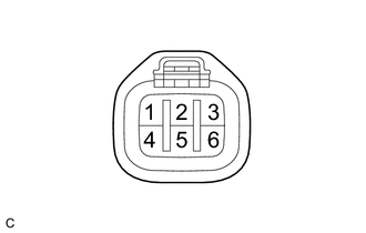
| *a | Front view of wire harness connector
(to EGR Valve Assembly) |
Disconnect the EGR valve assembly connector.
Turn the power switch on (IG).
Measure the voltage according to the value(s) in the table below.
- Standard Voltage:
Tester Connection Condition Specified Condition C53-2 (+B1) - Body ground Power switch on (IG) 11 to 14 V C53-5 (+B2) - Body ground Power switch on (IG) 11 to 14 V
- Result:
Result OK NG
OK
NG
Disconnect the EGR valve assembly connector.
Disconnect the ECM connector.
Measure the resistance according to the value(s) in the table below.
- Standard Resistance:
Tester Connection Condition Specified Condition C53-4 (EGR1) - C155-45 (EGR1) Always Below 1 Ω C53-3 (EGR2) - C155-43 (EGR2) Always Below 1 Ω C53-6 (EGR3) - C155-44 (EGR3) Always Below 1 Ω C53-1 (EGR4) - C155-42 (EGR4) Always Below 1 Ω C53-4 (EGR1) or C155-45 (EGR1) - Body ground and other terminals Always 10 kΩ or higher C53-3 (EGR2) or C155-43 (EGR2) - Body ground and other terminals Always 10 kΩ or higher C53-6 (EGR3) or C155-44 (EGR3) - Body ground and other terminals Always 10 kΩ or higher C53-1 (EGR4) or C155-42 (EGR4) - Body ground and other terminals Always 10 kΩ or higher
- Result:
Proceed to OK NG
OK
NG
Remove the EFI-MAIN NO. 1 relay from the No. 1 engine room relay block and No. 1 junction block assembly.
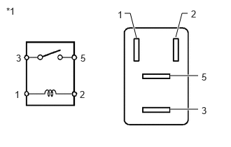
| *1 | EFI-MAIN NO. 1 Relay |
Measure the resistance according to the value(s) in the table below.
- Standard Resistance:
Tester Connection Condition Specified Condition 3 - 5 Auxiliary battery voltage not applied between terminals 1 and 2 10 kΩ or higher Auxiliary battery voltage applied between terminals 1 and 2 Below 1 Ω
Install the EFI-MAIN NO. 1 relay.
- Result:
Proceed to OK NG
OK
NG
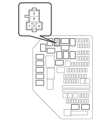
| *1 | No. 1 Engine Room Relay Block and No. 1 Junction Block Assembly |
| *2 | EFI-MAIN NO. 1 Relay |
Remove the EFI-MAIN NO. 1 relay from the No. 1 engine room relay block and No. 1 junction block assembly.
Measure the voltage according to the value(s) in the table below.
- Standard Voltage:
Tester Connection Condition Specified Condition 5 (EFI-MAIN NO. 1 relay) - Body ground Always 11 to 14 V 2 (EFI-MAIN NO. 1 relay) - Body ground Always 11 to 14 V
- Result:
Proceed to OK NG
OK
NG