HYBRID / BATTERY CONTROL PA10 HYBRID CONTROL SYSTEM(for LITHIUM-ION BATTERY) HV Battery High-voltage Line Circuit
DESCRIPTION
The cause of the malfunction may be the HV battery high-voltage line circuit.
Check the continuity in the high-voltage line from the HV battery to the inverter.
Check the connection condition and for an open circuit in the frame wire from the service plug grip, EV electric battery fuse and HV battery to the inverter and perform a function check of the system main relay.
| Area | Inspection |
|---|---|
| High-voltage circuit from HV battery to inverter | Check connection condition and for open circuit. |
| Service plug grip | Check connection condition and for open circuit. |
| EV electric battery fuse | Check for open circuit. |
| System Main Relay | Check operation condition as relay. |
SYSTEM DESCRIPTION
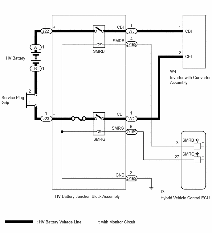
The HV battery high voltage is supplied to the inverter via the system main relay operation.
WIRING DIAGRAM
CAUTION / NOTICE / HINT
This diagnostic procedure is referenced to in the diagnostic procedure of several DTCs.
If the result of this diagnostic procedure is normal, proceed as directed in the procedure for the DTC.
- CAUTION:
-
Refer to the precautions before inspecting high voltage circuit.
- NOTICE:
- ·
After the ignition switch is turned off, there may be a waiting time before disconnecting the negative (-) auxiliary battery terminal.
·When disconnecting and reconnecting the auxiliary battery
- HINT:
-
When disconnecting and reconnecting the auxiliary battery, there is an automatic learning function that completes learning when the respective system is used.
PROCEDURE
- CAUTION:
-
Be sure to wear insulated gloves.
Check that the service plug grip is not installed.
- NOTICE:
-
After removing the service plug grip, do not turn the ignition switch to ON (READY), unless instructed by the repair manual because this may cause a malfunction.
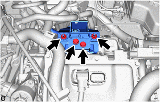
Check that the bolts for the HV floor under wire is tightened to the specified torque, the HV floor under wire is connected securely, and there are no contact problems.
- Specified Condition:
T = 8.0 N*m (82 kgf*cm, 71 in.*lbf)
Disconnect the HV floor under wire from the inverter with converter assembly.
Check for arc marks on the terminals for the HV floor under wire and inverter with converter assembly.
- Result:
Result Proceed to The terminals are connected securely and there are no contact problems. There are no arc marks. A The terminals are not connected securely and there is a contact problem. There are arc marks. B The terminals are not connected securely and there is a contact problem. There are no arc marks. C The terminals are connected securely and there are no contact problems. There are arc marks. B
Reconnect the HV floor under wire.
A
B
C
- CAUTION:
-
Be sure to wear insulated gloves.
Visually check the connection of the service plug grip to the HV battery. Remove the service plug grip and check for contamination.
- OK:
Dirt or foreign matter has not entered the connectors, and there is no evidence of contamination.
Install the service plug grip.
- Result:
Proceed to OK NG
OK
NG
- CAUTION:
-
Be sure to wear insulated gloves.
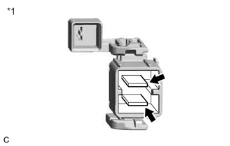
| *1 | Service Plug Grip |
Measure the resistance according to the value(s) in the table below.
- Standard Resistance:
Tester Connection Condition Specified Condition Service plug grip terminals Always Below 1 Ω
Install the service plug grip.
- Result:
Proceed to OK NG
OK
NG
- CAUTION:
-
Be sure to wear insulated gloves.
Check that the service plug grip is not installed.
- NOTICE:
-
After removing the service plug grip, do not turn the ignition switch to ON (READY), unless instructed by the repair manual because this may cause a malfunction.
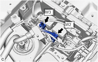
Check that the HV floor under wire is connected securely, and there are no contact problems.
Disconnect the HV floor under wire connectors from the HV battery junction block assembly.
Check for arc marks on the terminals of the HV floor under wire and the HV battery junction block assembly.
- Result:
Result Proceed to The terminals are connected securely and there are no contact problems. There are no arc marks. A The terminals are not connected securely and there is a contact problem. There are arc marks. B The terminals are not connected securely and there is a contact problem. There are no arc marks. C The terminals are connected securely and there are no contact problems. There are arc marks. B
Reconnect the HV floor under wire.
A
B
C
- CAUTION:
-
Be sure to wear insulated gloves.
Check that the service plug grip is not installed.
- NOTICE:
-
After removing the service plug grip, do not turn the ignition switch to ON (READY), unless instructed by the repair manual because this may cause a malfunction.
Disconnect the HV floor under wire connectors from the HV battery junction block assembly.
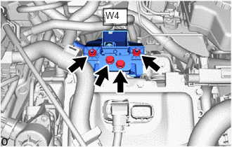
Disconnect the HV floor under wire connector from the inverter with converter assembly.
Measure the resistance according to the value(s) in the table below.
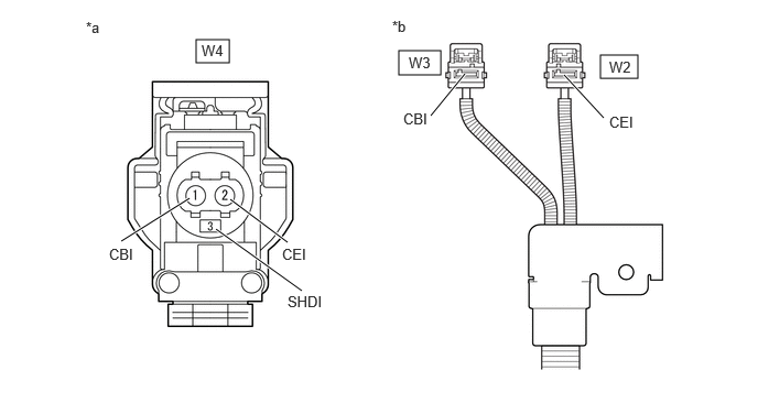
| *a | HV Floor Under Wire
(Inverter with Converter Assembly Side) |
*b | HV Floor Under Wire
(HV Battery Junction Block Assembly Side) |
- Standard Resistance:
Tester Connection Condition Specified Condition W4-1 (CBI) - W3-1 (CBI) Ignition switch off Below 1 Ω W4-2 (CEI) - W2-1 (CEI) Ignition switch off Below 1 Ω
- NOTICE:
-
Be sure not to damage or deform the terminal being inspected.
Using a megohmmeter set to 500 V, measure the resistance according to the value(s) in the table below.
- NOTICE:
-
Be sure to set the megohmmeter to 500 V when performing this test. Using a setting higher than 500 V can result in damage to the component being inspected.
- Standard Resistance:
Tester Connection Condition Specified Condition W4-1 (CBI) or W3-1 (CBI) - W4-3 (SHDI) and Body ground Ignition switch off 10 MΩ or higher W4-2 (CEI) or W2-1 (CEI) - W4-3 (SHDI) and Body ground Ignition switch off 10 MΩ or higher W4-1 (CBI) - W4-2 (CEI) Ignition switch off 10 MΩ or higher W3-1 (CBI) - W2-1 (CEI) Ignition switch off 10 MΩ or higher
Reconnect the HV floor under wire connector to the inverter with converter assembly.
Reconnect the HV floor under wire connectors to the HV battery junction block assembly.
- Result:
Proceed to OK NG
OK
NG
- CAUTION:
-
Be sure to wear insulated gloves.
Check that the service plug grip is not installed.
- NOTICE:
-
After removing the service plug grip, do not turn the ignition switch to ON (READY), unless instructed by the repair manual because this may cause a malfunction.
Remove the HV battery junction block assembly.
Measure the resistance according to the value(s) in the table below.
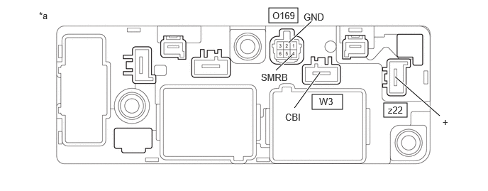
| *a | Component without harness connected
(HV Battery Junction Block Assembly) |
- | - |
- Standard Resistance:
Tester Connection Condition Specified Condition z22-1 (+) - W3-1 (CBI) Auxiliary battery voltage not applied between terminals O169-4 (SMRB) and O169-2 (GND) 10 kΩ or higher z22-1 (+) - W3-1 (CBI) Auxiliary battery voltage applied between terminals O169-4 (SMRB) and O169-2 (GND) Below 1 Ω
Measure the resistance according to the value(s) in the table below.
- Standard Resistance:
Tester Connection Condition Specified Condition O169-4 (SMRB) - O169-2 (GND) -40 to 80°C (-40 to 176°F) 20.6 to 40.8 Ω
Install the HV battery junction block assembly.
- Result:
Proceed to OK NG
OK
NG
- CAUTION:
-
Be sure to wear insulated gloves.
Check that the service plug grip is not installed.
- NOTICE:
-
After removing the service plug grip, do not turn the ignition switch to ON (READY), unless instructed by the repair manual because this may cause a malfunction.
Remove the HV battery junction block assembly.
Measure the resistance according to the value(s) in the table below.
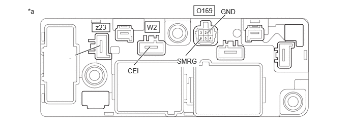
| *a | Component without harness connected
(HV Battery Junction Block Assembly) |
- | - |
- Standard Resistance:
Tester Connection Condition Specified Condition z23-1 (-) - W2-1 (CEI) Auxiliary battery voltage not applied between terminals O169-6 (SMRG) and O169-2 (GND) 10 kΩ or higher z32-1 (-) - W2-1 (CEI) Auxiliary battery voltage applied between terminals O169-6 (SMRG) and O169-2 (GND) Below 1 Ω
Measure the resistance according to the value(s) in the table below.
- Standard Resistance:
Tester Connection Condition Specified Condition O169-6 (SMRG) - O169-2 (GND) -40 to 80°C (-40 to 176°F) 20.6 to 40.8 Ω
Install the HV battery junction block assembly.
- Result:
Proceed to OK NG
OK
NG