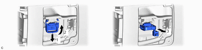
HYBRID / BATTERY CONTROL SERVICE PLUG GRIP REMOVAL
CAUTION / NOTICE / HINT
The necessary procedures (adjustment, calibration, initialization or registration) that must be performed after parts are removed and installed, or replaced during service plug grip removal/installation are shown below.
- CAUTION:
- ·
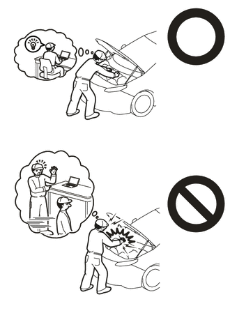
Orange wire harnesses and connectors indicate high-voltage circuits. To prevent electric shock, always follow the procedure described in the repair manual.
·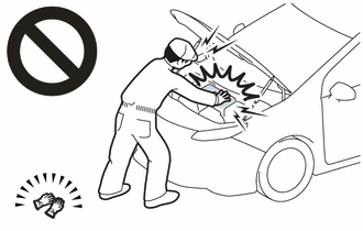
To prevent electric shock, wear insulated gloves when working on wire harnesses and components of the high voltage system.
- NOTICE:
-
After turning the power switch off, waiting time may be required before disconnecting the cable from the negative (-) auxiliary battery terminal. Therefore, make sure to read the disconnecting the cable from the negative (-) auxiliary battery terminal notices before proceeding with work.
- HINT:
-
When the cable is disconnected / reconnected to the auxiliary battery terminal, systems temporarily stop operating. However, each system has a function that completes learning the first time the system is used.
Learning completes when vehicle is driven Effect/Inoperative Function when Necessary Procedure not Performed Necessary Procedure Link Front Camera System Drive the vehicle straight ahead at 15 km/h (9 mph) or more for 1 seconds or more. (  202304,999999,_95,_139716,_0584193,RM1000000029F4C,)
PROCEDURE

 1.CHECK FOR DTC
Check for DTCs.
- CAUTION:
- ·
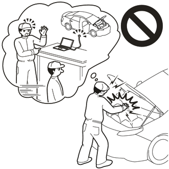
Confirm that DTC P0AA649 (Hybrid / EV Battery Voltage System Isolation Internal Electronic Failure), P1C7C49 (Hybrid / EV Battery Voltage System Isolation (A/C Area) Internal Electronic Failure), P1C7D49 (Hybrid / EV Battery Voltage System Isolation (Hybrid/EV Battery Area) Internal Electronic Failure), P1C7E49 (Hybrid / EV Battery Voltage System Isolation (Transaxle Area) Internal Electronic Failure) or P1C7F49 (Hybrid / EV Battery Voltage System Isolation (Direct Current Area) Internal Electronic Failure) are not output before removing or installing the HV battery. If this DTC is output, perform troubleshooting for this DTC first.
·To reduce the risk of electric shock, do not perform troubleshooting before checking for DTCs.
64490
2.REMOVE LUGGAGE COMPARTMENT SIDE TRAY ASSEMBLY (for M20F-FXS, M20G-FXS)
3.DISCONNECT CABLE FROM NEGATIVE AUXILIARY BATTERY TERMINAL
for M20F-FXS, M20G-FXS:
58441E
4.REMOVE BATTERY SERVICE HOLE COVER
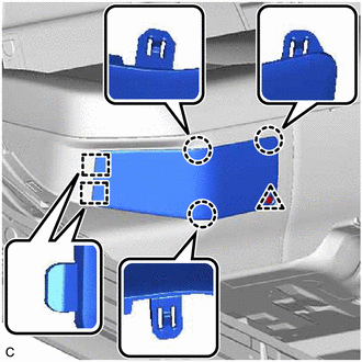
Remove the clip.
Disengage the 3 claws, 2 guides and remove the battery service hole cover.
G3834
5.REMOVE SERVICE PLUG GRIP
- CAUTION:
- ·
Be sure to wear insulated gloves.
·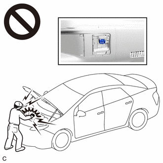
Do not inspect or service the high voltage system with the service plug grip installed.
·To reduce the risk of electric shock, make sure to remove the service plug grip to cut off the high voltage circuit before servicing the vehicle.
·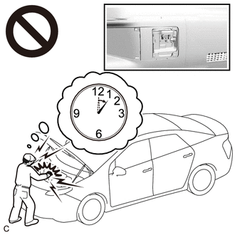
To reduce the risk of electric shock, make sure to wait at least 10 minutes after removing the service plug grip to fully discharge the high voltage capacitor inside the inverter with converter assembly.
·Keep the removed service plug grip in your pocket to prevent other technicians from accidentally installing it while you are servicing the vehicle.
- NOTICE:
- ·
After removing the service plug grip, turning the power switch on (READY) may cause a malfunction. Do not turn the power switch on (READY) unless instructed by the repair manual.
·Do not touch the terminals of the service plug grip.
·If the service plug grip has been struck or dropped, replace it.
- HINT:
-
Waiting for at least 10 minutes is required to discharge the high voltage capacitor inside the inverter with converter assembly.
While wearing insulated gloves, rotate the handle of the service plug grip and remove the service plug grip as indicated by the arrows, in the order shown in the illustration.